• This forum is the machine-generated translation of www.cad3d.it/forum1 - the Italian design community. Several terms are not translated correctly.

[aiuto] workflow progetto 3d

  • Thread starter Thread starter epasinet
  • Start date Start date

epasinet

Guest
Ragaz, I'm freaking out!
I want to try to make a project of a two-storey house with falde roof and windows with balconies in venetian in the simplest of cases.
after reading all the possible guides imaginable on the net I stuffed my sleeves and put myself to work.
I'm leaving!
file settings document>set document and set everything there is to set with unit of measurement cm and sheet size a1.
file settings document>set model choose 2planes without basement and set in the most trivial of the ways the share of the shiny foundation to -50cm; the ff share of the polished ground floor at 0cm the floor height at 270cm and thickness 50cm; the ff share of the polished first floor to 320cm the floor height to 270cm and thickness 50cm; the r share of the polished roof to 590cm.
active start the polished ground floor and for convenience design a rectangle of the internal dimensions of the perimeter walls of the building and then with the command "create walls" we pee around the walls without style of thickness cm40 with height of the gloss and that is 270cm.
then active the shiny first floor, design a rectangle on the outer perimeter of the walls of the ground floor and with the command creates loft create the foundation plate with altitude z -50cm and thickness 50cm.
I then activate the shiny second floor and with the same method I create the loft resting on the walls of the ground floor.
then activate the shiny first floor and take off the copied walls of the gloss that contains the walls of the ground floor.
taken from curiosity I want to see in 3d what I created and so active the unified view and imposed the view iso right front to see my first creation. (I note that if I make hidden lines it doesn't make me the whole model but only the solids present in the active polish!?!? Is that normal? ? )
then mistakenly disables the unified view and when I pass to the view in the plant it changes point of view only to the active gloss and so proceed to the change of view for each gloss, command+0 and ..sorpresa! Some of the walls were disaligned:
vabbè select the unsaligned elements and thanks to the smartcurson they put them in their place.
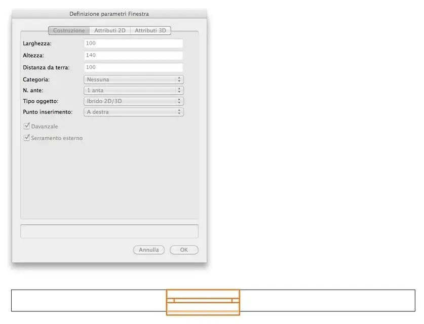
ok, then I decide to insert a window on the walls on the ground floor; I leave in fourth, open the curtain walls and clikko the architect window. clikko the fourth icon on the way bar to see the configuration panel and looks like a window with very few settings, I mention some, width, height, distance from the ground, category, no doors, type object, insertion point. .
but I want a classical window mounted inside the wall and with the shields mounted in axis to the thickness of the wall with opening to the Venetian?!? How do I do that?


For now I stop here because I think I already put enough meat on fire to discuss.

cmq the work in progress continues. .
 
Um...

1) breathing

2) activate the unified view of the glosses if you want to see that you combine in 3d
 
calmly... At first it happens to do some shit. to see all the lights and categories you have to set in the management window (lights, categories, etc.) what you want to see through the drop-down menu. At that moment you tell him if you want it in transparency, if you want to hook it or not, and other things... keep trying, but believe me, it's easier than it looks.
 
I also add that acquiring some experience it turns out that there is no one method to do things. you value depending on the model you go to build or even just how it is most convenient.
for example I divide the building for floors, then floor + ground floor walls on layer 0; floor + 1 walls on the sucessive layer, etc., but without assigning a quota to the layers but preferring to assign it directly to the objects. this because it happened to me for various reasons of having to then carry everything on a single layer.
however it takes a minimum of patience even to understand how to structure your own model... courage!
I do.
 
Thanks to all the boys.
I now realized that to manage the vision of the model in the various views I have to work with the "light options" present in the navigation palette.
therefore for those who need help with my own problem must open the navigation board that finds in the curtain tables. in the navigation palette you have to activate the second button at the top showing the list of the lights present in the model and changing the drop-down menu "polished options" are found various combinations of vision of the lights. the options are quite simple and you first try one by one rather than explain them!

I always feel unresolved. How come if I move a loft in a iso view when I go to see it in the plant really did not snap as I thought?! I make an example; Suppose I designed the ceiling, the ground floor walls, the basement floor and the first floor walls. active the unified view and change the point of view from "high/plant" to "iso right front". in the navigation table I apply the "filtra and attach others" option. select the ceiling and with the command moves, move the aforementioned ceiling over the walls of the first floor; to do this thanks to the smartcursor attach a lower edge of the ceiling to be translated and the snappo to a upper edge of the wall corresponding to the first floor. everything seems ok! then when I pass to the view "high/plant" I realize that such loft has not snapped as I thought but is completely disassato respect the whole model!! !

Okay, I answer myself because while I wrote, I understand and confirm if I'm right.
the error is that I to move the loft used the 2d selection tool while to do this it is necessary to use the appropriate 3d selection tool that is located in the modeling panel in the floating curtain "set tools". Unfortunately I understood that vectorworks reason in 2d and in 3d distinctly and therefore it is oppurtuno star careful to use the 2d tools when you intend to work on the screen plane and 3d tools when you intend to edit or create parts of the model on the three dimensions.

The question of windows is always open. how do I create a window with the shields as I want that in my area in the province of Venice all the projects have such shields and therefore it is not even such a particular thing!

thanks to all
Remember that you always move within 3d therefore, with the 2d tool, when you move not always you move in the appropriate directions ... you have to change from two views at least to have the exact position .... cmq is normal that you do it, with the experience you refine its use.
 
I ventured on the ladder.
I have to make a very simple scale. from the ground floor to the first floor for a jump of 320cm.
I'll attach a 2d scheme to make you understand how it should be.
I was discouraged because with the starlogic module it is almost unrealizable because it does not accept the rise between the two landings. .
What do you recommend, I need to model it in 3d with modeling tools?
 

Attachments

  • SCALA.webp
    SCALA.webp
    10.4 KB · Views: 9
What do you mean, she doesn't accept you? ............... is it that you confuse the rise of the single step with that between the landings? ;)
 
What do you mean, she doesn't accept you? ............... is it that you confuse the rise of the single step with that between the landings? ;)
look marco do first to make a quick test with starlogic, because to make this scale I think you have to choose the type u with three ramps and two landings and tell him that the ramp between the two landings has only one raised. the steps have weighed from 30 and are 18 raised to win 320cm from floor to floor. then if you can realize you can edit the first step to round it?

cmq if you can console yourself when I studied archicad there was no way to do this type of scale, the only program that generated it automatically without blinking was addcad.
cmq to model it in vector you say that it is correct to draw a polygon that represents the profile of the first ramp with the first landing and then to extrude it linearly of 1ml that is the width of the ramp, then with the same method to realize the second ramp with the second landing and finally to rasp the two ramps in a symbol? ? ! ?


thanks to all
cmq to model it in vector
 
yes you can "separate" (explode) the parametric object, obtaining an editable element with normal functions. Keep in mind that it is a "hybrid 2d/3d" object, so if you separate it while you're in sight plant it gets part 2d and vicerversa if you see 3d. If you want to get the two objects, you can: duplicate the object, separate it twice (one in 2d and one in 3d), edit the two parts as you need, create a 2d+3d hybrid symbol that includes both.
 
yes you can "separate" (explode) the parametric object, obtaining an editable element with normal functions. Keep in mind that it is a "hybrid 2d/3d" object, so if you separate it while you're in sight plant it gets part 2d and vicerversa if you see 3d. If you want to get the two objects, you can: duplicate the object, separate it twice (one in 2d and one in 3d), edit the two parts as you need, create a 2d+3d hybrid symbol that includes both.
Thank you! I didn't know you could "create" hybrid symbols 2d/3d!!
I believe that this aspect is extremely crucial for a good 3d design.
I quote in some concrete attempt and then of course I will write a miniguide on the next replies so that this thread serves help to all neophytes of work vectors.
 
You guys are trying! !

apart from that I am disadvantaged because in my demo version of vectorworks architect 2010 sp3 r4 I do not have the complex architect window and at least the doors because as you see in the annex I have a banner for the setup of the architect window.. :

I created a window but I have no idea how it explodes and hard to find the description of the process as well as on the manual issued by videocom! !

I'm sad. .
 

Attachments

  • Finestra Architect.webp
    Finestra Architect.webp
    15.8 KB · Views: 9
also in the demo version you can use the complex door and architect window. it is sufficient that you activate the appropriate mode in the mode bar: the first two icons control the operating mode (simple, complex).

exploding a parametric object is quite simple: put it in the view you need (top or above) and choose the command "instruments > separate". vw warns you if you really want to separate it: You tell him yes.
Thank you, thank you, thank you!
I'm in debt with everyone. .

enrico
 
Thank you, thank you, thank you!
I'm in debt with everyone. .

enrico
I'm not sure, but I think we're going down the same road. I to learn well I began to want to work immediately in 3d\2d and I put hard patience the endurance of lory.b with this discussion http://www.cad3d.it/forum1/showthread.php?t=15544 and after hard labors I had understood that perhaps the initial best approach is to take a good moment of only 2d, learn to use the program, and if you have to do the 3d go parallel. if you immediately proceed with the hybrid risks, believe me, to lose more time understanding the hybrid object than to make a drawing. then you don't learn to save on forms, and maybe after so long you work on a model you want to do a section and you plant your computer. I recommend you, because I passed and I would have liked that someone had told me well before, that 2d is 2d 3d is 3d, at least at the beginning. then vabbè, for example, except for the forum of the videocom has done a good job, but in short, you can arrive calmly. then you will understand that with vector there are so many limits in 3d. I those that I really can't conceive and of which I made a reason are 1) impossibility to make more than a lap of ramp with the starlogic 2) the bad system of snap 3d of 2009, than when apparently with 2010 it is improved eh.. but for the moment these 2. Then you will see. Still continues to explore, I do not want to propose to stop you, but only to be careful because coexistence 2d 3d is not so spontaneous and immediate, especially if you are at the first weapons as I am. :finger:
 
I agree with zetadierre on those that can be limits in working completely in parametric and in the case:
1) starlogic module - true, there are strong geometric limitations, but I can assure you that in videocom they are working fullspeed to solve them
2) 3d snaps in vectorworks were never good, rather they were almost absent. the 2010 version represented a turning point (almost epochal) and building in 3d is now really within reach of everyone.
future versions of vectorworks will certainly aim in these directions: absolute improvement of parametric modes (bim), improvement of ease of use in 3d, consolidation of part 2d, which in qualitative terms is distant from all other cad. as Americans say: Stay tuned
 
thank you guys for the precious tips.
But if I can afford to say, I don't think that vector is so behind compared to competition. it is true that I started with 2010 ke to say of everyone has made a nice jump with snap3d but I repeat that I do not find it so disconcerting. Think that 18 years ago I started working with the amazing bagh architrion, then I went to autocadlt with which I made several views in 3d. Then I bought addcad that I used with satisfaction. Over the years I have learned 3ds that I detest and have promptly abandoned, to date model and high-level rendering with lightwave3d, fprime and maxwelrender. and when I make design contests for prototype model with rhino nurbs. I've been studying for a few months also archicad 13 but hasn't bought me at all. .
I'm just saying that to make you understand that I'm not in the first place and I'm used to splitting from one program to another.
after so many years of work with the 3d I feel the need of the bim, of the 3d aimed at the development of the architectural project and not of the inflated rendering end to itself.. .
I believe very in vectorworks despite knowing it for a few months, because it seems to me that it is a software that can offer the right creative freedom and design that many bim competing software fail to have. Moreover the system of tables and spreadsheets is very powerful and can help in the difficult phase of computation and direction work.
That said, after developing the environment 2d and the ability to integrate with the dwg extension I want to understand the workflow 3d bim to understand if it is the right software for me and that I can finally buy!
Unfortunately videocom does not have the ability to bare the true workflow that I seek; publish interesting and well-made guides but very fragmented and devoid of that logical thread that a designer seeks for a complete evaluation of the product. I don't understand if they behave like this to bypass structural weaknesses of the software or if they do it for shortages of resources for development a very full tutorial.

I strongly hope that vectorworks architect is what I have in mind and that I have promised to strive to learn until exasperation. If I can close an accetable workflow that can assist the whole hybrid design process with computation support, I will personally realize my guide so as to reward the software and spread its knowledge in Italy where most of my fellow architects do not even know that it exists! !

thanks to all

enrico
 
Unfortunately videocom does not have the ability to bare the true workflow that I seek; publish interesting and well-made guides but very fragmented and devoid of that logical thread that a designer seeks for a complete evaluation of the product. I don't understand if they behave like this to bypass structural weaknesses of the software or if they do it for shortages of resources for development a very full tutorial.
Why not contact videocom? develop tutorials is complex and you are always looking for ideas and collaborators. You can say I'll send you:cool:
 

Forum statistics

Threads
44,997
Messages
339,767
Members
4
Latest member
ibt

Members online

No members online now.
Back
Top