PiegatoreSolidworks
Guest
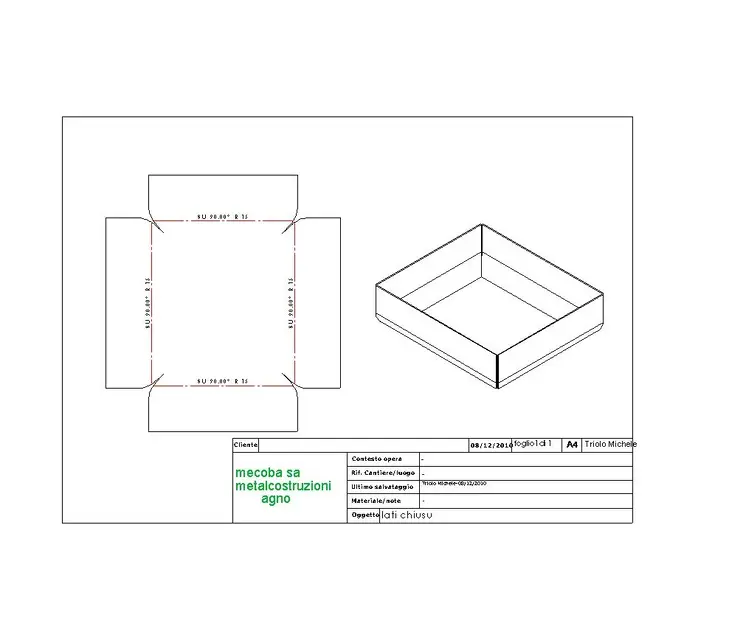
So I'm waiting for the time to be wrong, but tell me you experts what difference between these 2 identical but different pieces on the corner board?
I press that I use swx 2010 sp4 if not mistaken.
I opened this post because today I found myself doing a similar piece and the air on the corner came of 5mm and I stayed of mer..! I trusted 100% software but from now on I will never do it again!!!! !
I'm waiting for news, thank you.
(who has the 2011 version can create a new file and check if the problem is there too?)