
• This forum is the machine-generated translation of www.cad3d.it/forum1 - the Italian design community. Several terms are not translated correctly.

[lamiera] welded edges

  • Thread starter Thread starter Matteo
  • Start date Start date

Matteo

Guest
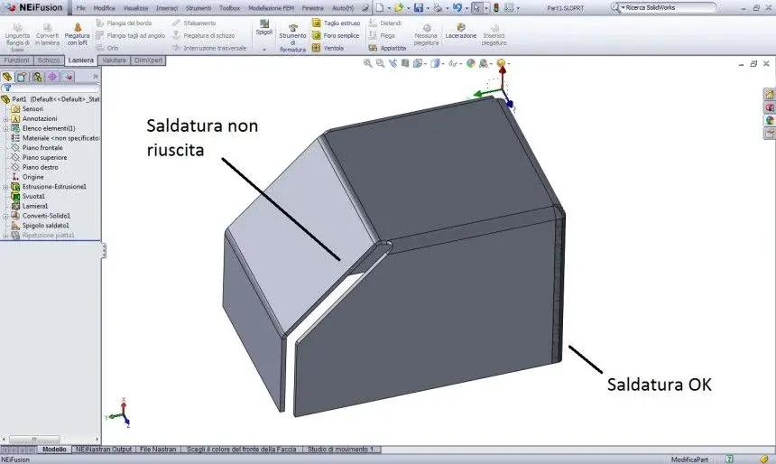
I have difficulty in running the command "spigolo welded" on a model in which the edge is tilted. I attach an example image.

assistance I don't know how to help (the product is not "official" swx but a version provided in the package infusion so the assistance doesn't know much about cad and more than anything follows the fem part).

I also attach the file prt.

thanks for the suggestions!
 

Attachments

  • lamiera.webp
    lamiera.webp
    37.2 KB · Views: 86
  • Part1.zip
    Part1.zip
    132.7 KB · Views: 14
we assume that I take your project for good and by project I mean the space left between the legs (2 mm) and how they close the folds.
said this, the command you use fits in many cases, except for this situation and the parameters you entered, which I take as untouchable.
as you have noticed, the command does not complete due to that deformed surface located in the upper intersection of the two lembi.
if we take everything for good, to perform the desired operation, you will have to use the command 'insert folds' instead of 'converted in sheet'.
the laceration that will arise will be different and will allow the use of the desired command.

I can't send you the file as I use 2011.
 
sì, con insert folds and assigning the right parameters (make tests between fitting radius and laceration play) the function goes to good end.

above all if you use the converti in lamiera is not the case before emptying; That function "incorporated" and she does everything.

greetings
Marco:smile:
 
I take advantage to ask you an impression: Do you use the convert in sheet metal? I used it sometimes but, in addition to leaving more game between the faces of a normal emptying+laceration+ insert folds, it seems particularly heavy to recalculate for swx. did you have the same impression?
 
I take advantage to ask you an impression: Do you use the convert in sheet metal? I used it sometimes but, in addition to leaving more game between the faces of a normal emptying+laceration+ insert folds, it seems particularly heavy to recalculate for swx. did you have the same impression?
for the game, it is a value to change to the creation of the function, if known in the attached file the default value was left, or 2 mm.
I'm not using that feature a lot, I found a bug:
the k factor value added to creation, is not possible editable.
to be precise there is the possibility to change it, but you have to act on the individual
bending by editing one to one value k.
We noticed yesterday, a colleague of mine threw 300 chf of sheet for
This mistake.
if it is true that some functions are innovative, those already present, even for a long time, present
really annoying dysfunctions that create a sense of non-security, you have to
recheck, to sample, some folds.
returning to topic, I would recommend the use of a very small radius, we say
between 0.1 and 0.005.
by making evidence you realize the advantage. (click near the folds.
Moreover, standardizing the bending rays, unless you have special cases, you can also streamline the table for fk.
I too, like sampom, suggest you avoid emptying usant converts into
sheet metal.
greetings:
 
I'm not using that feature a lot, I found a bug:
the k factor value added to creation, is not possible editable.
to be precise there is the possibility to change it, but you have to act on the individual
bending by editing one to one value k.
the k factor you can edit it in the function before the sheet metal convert.
There is no bug in this case.

Moreover recommend to perform the bending radius of a value tending to the living edge, goes against every logic of common sense and design within the scope of the die-folding.
at your house do whatever you want, but don't give such advice as if they were the solution to all development problems.
your theory is not supported by any technical information.
development calculation is centered on the fold radius + a constant.
If you omit the fold radius...the k factor you could find on the material specifications or from your evidence, you can put it... .
there are formulas and should be used + some adjustment in case you need precision of the tenth order.
 
the k factor you can edit in the function before the sheet metal convert.
There is no bug in this case.

Moreover recommend to perform the bending radius of a value tending to the living edge, goes against every logic of common sense and design within the scope of the die-folding.
at your house do whatever you want, but don't give such advice as if they were the solution to all development problems.
your theory is not supported by any technical information.
development calculation is centered on the fold radius + a constant.
If you omit the fold radius...the k factor you could find on the material specifications or from your evidence, you can put it... .
there are formulas and should be used + some adjustment in case you need precision of the tenth order.
Hoooo... Not bad you showed me. . .

Come on, solid. It's not the first sheet I make.. .
control better you, edit that value, yes, visually factor k, change, but if you control the development you will see that mon does. I don't write things wrong.
on the fact of the rays, I'm not answering you anymore I've already debated enough on this and after 11 years and thousands of tons of worked sheet, I have wide shoulders enough to give that advice, good replica.
who will, will try and realize the advantage, in terms of time, of that
strattagem.
if it had not been possible to attribute those rays for tennical reasons, I am sure that the sw
He wouldn't have allowed it, since you can, I do.
You know, I'm used to drawing in 3d, not in 3.... (who uses sheets can understand me)
 
I'll attach a file so at least you'll spend the morning:
I set, to the sheet metal conversion, a factor k of 0 (zero).
Here, now, change that value from where you say (that I didn't know...:biggrin:) and then tell me if you change your development.
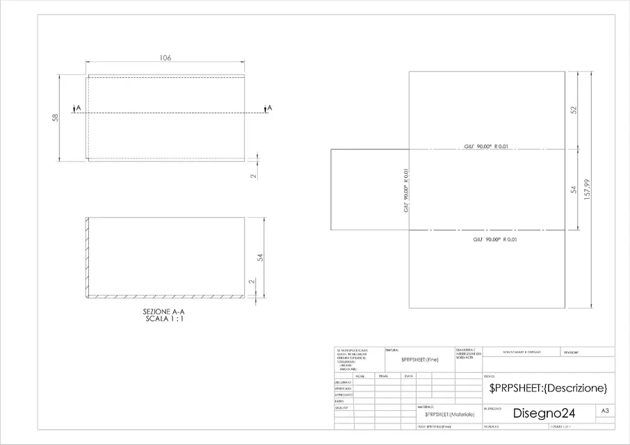
the answer is : development remains equal, the only way to update to value
of factor k is to click on the sign + of "solid converts1" and to enter into change of the net bends, una ad una...
Now that I tried on this pc, I tested on 5 cars!!
Good divetition.
...and now I go back to bed that in an hour I have to get up...:redface:


if someone else will have the goodness to try it will be an additional test
before you communicate it to the assistance.
 

Attachments

if you omit the fold radius...the k factor you could find on the material specifications or from your tests, You can put it... .
now you put on good buzz and explain to me by thread and by sign (you can also mime it) what it wants
say your sentence (as if you were explaining to a 5-year-old, please).... and try to be convincing (especially the bold) because I'm not stupid (poco)...and maybe the complete, ehh!.
What would you suggest, that in 11 years of solidworks I have developed non-consistent developments?
or did I get them out?
that che gaurdacaso 90% of my work is on the plates (every so we pieghiamo also minchi ste of plates. . )
What else?
Have a good day.
 
I'll attach a file so at least you'll spend the morning:
I set, to the sheet metal conversion, a factor k of 0 (zero).
Here, now, change that value from where you say (that I didn't know...:biggrin:) and then tell me if you change your development.
the answer is : development remains equal, the only way to update to value
of factor k is to click on the sign + of "solid converts1" and to enter into change of the net bends, una ad una...
Now that I tried on this pc, I tested on 5 cars!!
Good divetition.
...and now I go back to bed that in an hour I have to get up...:redface:


if someone else will have the goodness to try it will be an additional test
before you communicate it to the assistance.
confermo il bug.
 
now you put on good buzz and explain to me by thread and by sign (you can also mime it) what it wants
say your sentence (as if you were explaining to a 5-year-old, please).... and try to be convincing (especially the bold) because I'm not stupid (poco)...and maybe the complete, ehh!.
What would you suggest, that in 11 years of solidworks I have developed non-consistent developments?
or did I get them out?
that che gaurdacaso 90% of my work is on the plates (every so we pieghiamo also minchi ste of plates. . )
What else?
Have a good day.
You're not talking to someone who folds the plates every now and then.
our products are all made of sheet metal.
we are a company with 1000 employees and more.
we have automated and centralized warehouses, laser cutting and die-cutting.
we have robotic welding systems.
painting plants.
the amount of sheet we move per day you did not present it.
our files are used throughout the process, from laser cutting, at bending and finally to welding.
We cannot allow ourselves to be wrong with development, for the simple reason that what part of the order of that code, there is no test phase.
Just leave.
development is linked to the fold radius.
If you take me to zero the radius.. .high everything, also because it is also tied to the fold corner.
I'll tie you a side file and you'll tell me how much development is.
apart from your stratagem, the fact of not making a part of sheet as in reality... there could be errors in the design phase.
holes that do not take into account the proximity of the fold radius, canned objects, cover, etc...

apart from your case and perhaps another, other users fall in general use real formulas and bent rays for their sheet metal parts and develop their products properly.

I do not context that you do it at your home, I context that you give advice on a customised procedure that probably cannot be implanted in other realities, while there is a well-documented procedure on technical textbooks, official and used in all cad.
 
confermo il bug.
thanks for the test. :finger:
Today, or at the latest Monday, I will break the bales to assistance.
You're not talking to someone who folds the plates every now and then.
our products are all made of sheet metal.
we are a company with 1000 employees and more.
we have automated and centralized warehouses, laser cutting and die-cutting.
we have robotic welding systems.
painting plants.
the amount of sheet we move per day you did not present it.
our files are used throughout the process, from laser cutting, at bending and finally to welding.
We cannot allow ourselves to be wrong with development, for the simple reason that what part of the order of that code, there is no test phase.
Just leave.
development is linked to the fold radius.
If you take me to zero the radius.. .high everything, also because it is also tied to the fold corner.
I'll tie you a side file and you'll tell me how much development is.
apart from your stratagem, the fact of not making a part of sheet as in reality... there could be errors in the design phase.holes that do not take into account the proximity of the fold radius, canned objects, cover, etc...apart from your case and perhaps another, other users fall in general use real formulas and bent rays for their sheet metal parts and develop their products properly.

I do not context that you do it at your home, I context that you give advice on a customised procedure that probably cannot be implanted in other realities, while there is a well-documented procedure on technical textbooks, official and used in all cad.
bé, what to say, you were very clear and for that I thank you.
the context in which I work, me and my colleagues, is "lightly" different from yours.
we are a small company with only 25 employees.
I have to admit that maybe I thought small, but in our little one
until today we have produced without problems, calculates that we are tertisti
and customers are very demanding... but until today we have always delivered
dimensional tolerance pieces perfectly in line with what is required
from various customers (we work for different multinationals).
you are perfectly right but we have adapted the working method based
the amount and complexity of our work.
we tried to standardize in that way to contain design costs, building relatively few pieces at a time (we believe artisans) we have the objective need to be competitive in the part
theoretical (preparate files for t/laser-t/water-puncher) of the execution of the contract.
in specific cases, as evidenced, we draw the pieces as really
will come into reality for the reasons you have exposed, the remaining we conceive them
more "simplicily" with fictitious bent rays.
post something as well, but consider that our developments are processed on the basis of
to the removal/extension parameters of our fold molds, so they could
disconnect from your development.
Thank you again!
 
we tried to standardize in that way to contain design costs, building relatively few pieces at a time (we believe artisans) we have the objective need to be competitive in the part
theoretical (preparate files for t/laser-t/water-puncher) of the execution of the contract.
in specific cases, as evidenced, we draw the pieces as really
will come into reality for the reasons you have exposed, the remaining we conceive them
more "simplicily" with fictitious bent rays.
post something as well, but consider that our developments are processed on the basis of
to the removal/extension parameters of our fold molds, so they could
disconnect from your development.
Thank you again!
We also support third parties for prototypes.
the cost of tooling for 1 or 2 pieces can not be charged (the big companies have the cost centers for each department), moreover the production has priority and must be planned to occupy 100% the operator and the machines.
so all the prototypes are made out and the development for laser cutting is very important.
if there were no formulas for development calculation, for each supplier we should use different solutions, while using 'official' formulas we unleash from the supplier and we dedicate the time due to the project.

I attach a step without bent rays, because these affect development and then approach your working method.
calculate me the development and put me the 2 maximum dimensions.
I don't care about the solidworks file, I just need an image.
the piece is very simple.
 

Attachments

I usually design structures and with sheet metal we often make structural parts. the thickness of the sheets we use ranges from 1 mm up to 300 mm and sometimes we come to fold very high thicknesses, we say however that it is very frequent to bend the sheets with thickness up to 15-20 mm.
when calculating developments I have to customise them for those who will realize them and often, they are quite different between one supplier and the other.
I also bought several books and documented how to calculate developments, but as I told you, on sheets of a certain thickness the formulas are valid to approach the real thickness, not to correctly realize the details.

with regard to the rays I never model to radius 0 since, being sheet for important structures, the radius is fundamental to not incrude (and then encrypt) the fold area. for me it is essential to quote the radius on the design and to claim that those who make the plates do not fall below that radius value. if you have to buy a quarry or take it or change supplier, there are half certified entities that, rightly, demand perfect adherence between the project and the details realized.
Moreover, as you rightly say, if there are transversal plates to rinse a fold it is good to have under eye the exact encumbrances.
 
when calculating developments I have to customise them for those who will realize them and often, they are quite different between one supplier and the other.
I also bought several books and documented how to calculate developments, but as I told you, on sheets of a certain thickness the formulas are valid to approach the real thickness, not to correctly realize the details.
when I used the term customizing with mike, I was talking about a procedure related to their modus operandi.
if instead you talk about customization of the factor-k linked to the supplier, then it is normal that there is discordance.
discordance is linked to the use of the machine and therefore you have to correct the factor-k.
the fold radius is tied to the quarry and tonnage that is used to bend.
here are official formulas and if the suppliers used them... you would be even less discordance.
there are designers who of the minimum edge and other things stick or do not know them, creating plates that to be produced must use ton out of safety or out of formula, requiring a calculation of its own development.
Sometimes suppliers make folds with tons tending to coniatura.
That is why of these adjustments.

we agreed with our supplier to create a report on the creation of the piece, from the quarry, to the punch and tonnage used.
these must follow our specifications, which allow us to have a certainty about what we produce both as a prototype and as a series production.
 
post something as well, but consider that our developments are processed on the basis of
to the removal/extension parameters of our fold molds, so they could
disconnect from your development.
Thank you again!
I recommend, do not do it really to be able to find the correct development.:finger:
 
I recommend, do not do it really to be able to find the correct development.:finger:
only one solid thing;
If you place an example of that type, without indicating material and rays you want to get (so quarry and knife and various parameters to use) there will be no "correct development" (i.e. unique for all), but a "correct finished detail" that respects the size of the fold (as for example), ready to be mounted. and this is the objective data.
just for the reasons (all agree) so far expressed.

only doubt in your piece are the 2 ø6 holes in the "flangia" below. are too much on the fold, not to "invade" you should give rmax 2mm that for a sp. 25/10 is definitely too little.. This would be some sort of "coniatura" you were talking about.

greetings
Marco:smile:
 
I recommend, do not do it really to be able to find the correct development.:finger:
Absolutely not!
we do not do the tests before cutting the piece "real", we produce
without sampling anything.
later images of developments, to vary I also calculated development
with different materials and different rays.

marco exposed what I would write, plus 70% of the folds
we do are in "air".
I have a 23-year experience in this field, 10-12 of which have been in the workshop, quince, bending machine, punching machine, cutting water and now for 5 years
also laser cutting.
I have folded, unlike 99% of subscribers to this forum, sheet
since I was 20 years old with, at the beginning, development traced directly
on the sheet... that not knowing (the sheet), contains my object. . .
we used to track wagons and carter of all kinds, not boxes with straight corners and "simple" folds.
I do not fear any object to draw with sw for real production.
I have friends bending sheets every day, and adopt the ns itself
working system. returning to your piece, to be able to make the holes in the lip, we would do them
from diameter 2 then enlarge them to drill.
If instead it was a million pieces, perhaps equipping with a large quarry only 6 mm would be possible. . but in coniatura.. .
 

Attachments

only one solid thing;
If you place an example of that type, without indicating material and rays you want to get (so quarry and knife and various parameters to use) there will be no "correct development" (i.e. unique for all), but a "correct finished detail" that respects the size of the fold (as for example), ready to be mounted. and this is the objective data.
just for the reasons (all agree) so far expressed.

only doubt in your piece are the 2 ø6 holes in the "flangia" below. are too much on the fold, not to "invade" you should give rmax 2mm that for a sp. 25/10 is definitely too little.. This would be some sort of "coniatura" you were talking about.

greetings
Marco:smile:
You're right.
I forgot to tell you the material.
is steel dd11 (steel ductile for die-folding).
for the rest is derived from the formulas found on the books.
As you well know, the fold radius, not being a coniatura, is tied to the used quarry and tonnage etched.

for your doubt, this is just an example of what it means to design without stratagems.
If you used the fold radius as mike suggests, you wouldn't notice.

for formulas, find them on solidworks example files, on vademecum (which all have) and on google.
 

Forum statistics

Threads
44,997
Messages
339,767
Members
4
Latest member
ibt

Members online

No members online now.
Back
Top