cacciatorino
Guest
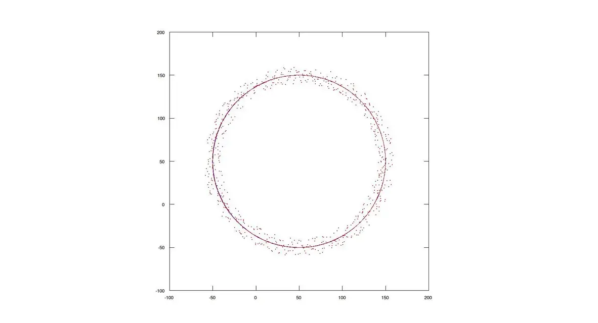
But I'm sorry, the center of an arch is not on the arch itself but well moved to the center. doing as you say maybe you can estimate the center with good precision but not the radius.you have to divide in three circular sectors the cloud of points (120°), for each sector to make the arithmetic average of the cordinate (x1+x2...)/n; (y1+...)/n: (z1+...)/n, points. find the three points with cooedinate x,y,z. through which you build your circumference. the programs I know with double clik above the point give me the coordinates of the point.

 a priori cannot know how the points are distributed? but do you do the relief, or do you find the measurements scattered on the ground near the relief zone?
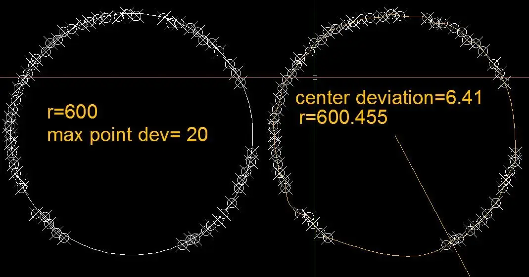


") = [1, cos(t(i))];
= [1, cos(t(i))];