• This forum is the machine-generated translation of www.cad3d.it/forum1 - the Italian design community. Several terms are not translated correctly.

corner bracket

  • Thread starter Thread starter anca91
  • Start date Start date

anca91

Guest
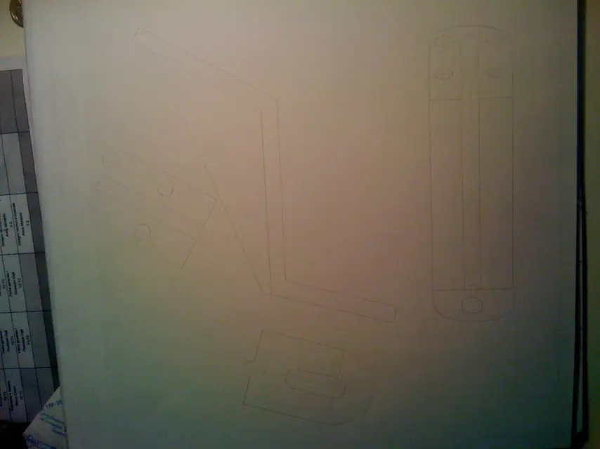
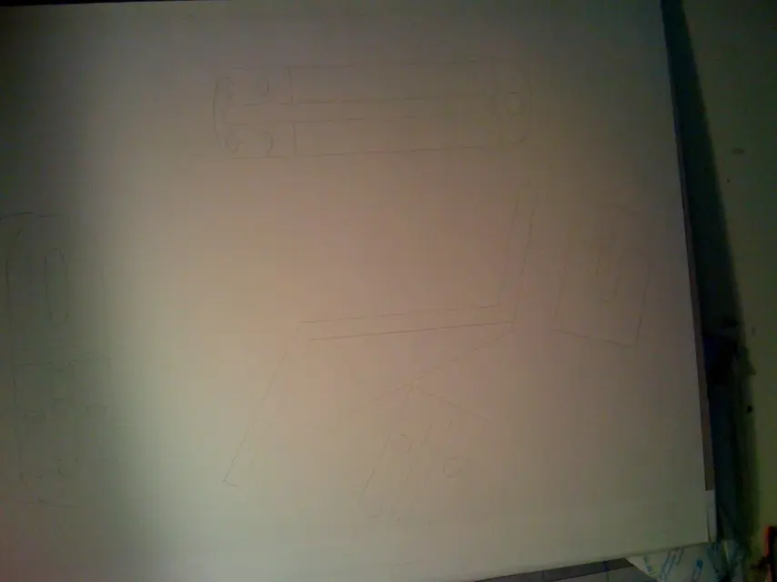
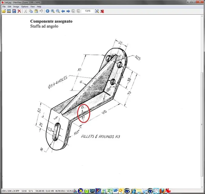
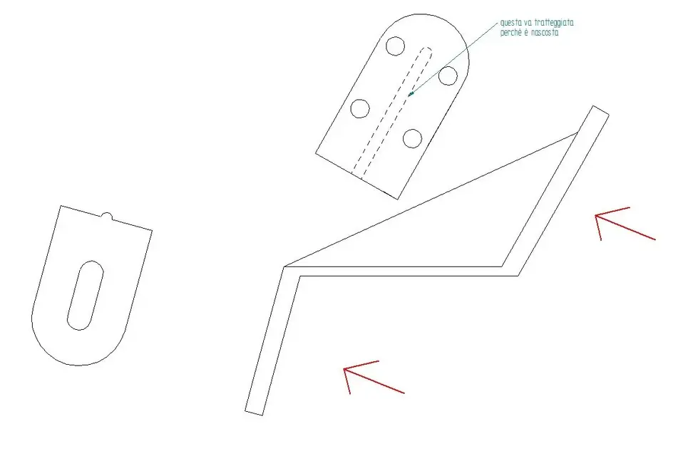
gent.mi colleagues, I'll take you back to the table that has made me refer my prof for 4 times I hope you can help me. The table in question is an orthogonal projection with auxiliary views of a non-mechanical component, I'll put what I did and I'd like you to help me understand how it is done. My prof told me I was wrong to do the thicknesses.
thanks in advance cordial greetings andrea :smile:
 

Attachments

  • cad.webp
    cad.webp
    368.8 KB · Views: 66
  • IMG_0261.webp
    IMG_0261.webp
    103.6 KB · Views: 73
@anca: Now I see you haven't introduced yourself.
before posting read the rules and presented (it is a golden rule of forums!)
your design in the photo or is wrong or there is a reflection that surmounts views.
so I don't understand anything, or you put something better on it or you do it again and place it.
you cannot claim to give judgments on something unjustable!
 
unfortunately the light is bad here is a round of photos
 

Attachments

  • 024.webp
    024.webp
    79.2 KB · Views: 58
  • 023.webp
    023.webp
    93.2 KB · Views: 41
  • 022.webp
    022.webp
    83.9 KB · Views: 36
  • 021.webp
    021.webp
    77 KB · Views: 30
Fig. 1
The whole thing left is wrong. The piece in that view is wrong? Is he tilted? the top view shows the two faces then surmounted, as by magic, appear staggered.
lack live edges, fittings, etc.
so, at first sight.

Maybe if you name the views you would understand better, but I think prof. is right.
 
I'd rather criticize my questionable talents as a designer, or at least give me an idea as you should do, wouldn't it be bad what you say?
 
What do I have to do, maybe take back the drawing?
I ask you a question: do you know how to make the orthogonal projections of a piece?
I'm telling you that a view is wrong and why you say that the two faces on the left view should be aligned and not staggered.... What more do you want?
And then, you put something that you can see right, ecchecavolo!
I don't know what to say.
Why don't you do it in autocad and then place the pdf?
 
@ anca91 My prof told me I was wrong to do the thicknessesthe prof. in the specific which thicknesses indicated to you that they are wrong? or was it generic?
the pictures you posted you don't understand anything, do some decent photos as the colleague told you.
also of this particular must you only make views and projections or even share it? Do you have a book to follow how to make orthogonal projections? What are the thicknesses to be used for views, axes, quotas, sections, hidden lines etc?
@ anca91 unfortunately the light is bad here is a round of photostake an outdoor photo with sunlight not directed on the sheet or if you have the option to scan the drawing sheet.
@ anca91 rather than criticize my questionable skills as a designer I gave me a hand to remake it ex novo... you try to make things understand to the people who require them, but don't expect us to do the drawing again, you'd waste only time because no one here is going to do the school tasks of others.
@ anca91 or at least give me an idea how you should do it wouldn't be bad what you say? If as already said places of decent photos we can help you better.
 
@ tequila you try to make things understand to the people who require them, but don't expect us to do the drawing again, you'd waste only time because no one here is going to do the school tasks of others.In fact I'm trying to figure out how to make this table I don't want you to make it to me... I'm an engineering student, not a professional copyer.

@ tequila

My teacher told me that the thickness that I have made is seen in the vertical view (to be the one on the right) requires a thickness that must be done in another way, but from the book that I use does not indicate how the thicknesses are performed.

Moreover this table does not require quotation is written in the first photo I sent, the bevels, the fittings are indicated in the same that as soon as I posted you .

I made a table in autocad ahime are a pop also in that so I would beg you to give me a hand from scratch.

If someone of good will, who has no problem with my person for this table is willing to stand by and help me understand what is not to be rewarded by a big thank you and of course it would go about the relationship that would be created between us, as well as possible future help; when perhaps I will be more experienced, for the other users of the same forum .

cordial greetings andre
 

Attachments

I am not the one who draws it is the delivery of the prof. That is the model and from that I have to do the orthogonal representation in 2d
 
@ tequila you try to make things understand to the people who require them, but don't expect us to do the drawing again, you'd waste only time because no one here is going to do the school tasks of others.In fact I'm trying to figure out how to make this table I don't want you to make it to me... I'm an engineering student, not a professional copyer.

@ tequila

My teacher told me that the thickness that I have made is seen in the vertical view (to be the one on the right) requires a thickness that must be done in another way, but from the book that I use does not indicate how the thicknesses are performed.

Moreover this table does not require quotation is written in the first photo I sent, the bevels, the fittings are indicated in the same that as soon as I posted you .

I made a table in autocad ahime are a pop also in that so I would beg you to give me a hand from scratch.

If someone of good will, who has no problem with my person for this table is willing to stand by and help me understand what is not to be rewarded by a big thank you and of course it would go about the relationship that would be created between us, as well as possible future help; when perhaps I will be more experienced, for the other users of the same forum .

cordial greetings andre
do me a courtesy, save the file in autocad format 2000 so even those who use dated versions like the undersigned (lt 2009) can open.
I have however opened it with solid edge and first impact it seems to me to understand that the thickness of the central part (and not of the lines as I imagined before) is different and not uniform as the 3d design (see image)
 

Attachments

  • staffa.webp
    staffa.webp
    22.6 KB · Views: 32
  • cc.webp
    cc.webp
    93.8 KB · Views: 32
In fact, what I posted to you was just a sketch, the thickness to which I refer and to which my teacher was referring was the one on the vertical and plant views, to intellect the one made with k line
 
In fact, what I posted to you was just a sketch, the thickness to which I refer and to which my teacher was referring was the one on the vertical and plant views, to intellect the one made with k line
opening it with other cad I do not see lines styles. try to save in dwg 2000
Also you have to indicate with freccies the projections from where you look at the piece otherwise you can confuse.

Among other things the projection below is not correct if you look at it from the arrow I indicated, moreover for both you should understand if you make a partial projection of the piece (for which to indicate a broken line of interruption) or otherwise you have to draw it all.

ps: write that you are at the engineering faculty, but are you from a technical institute or high school? Have you ever made mechanical or technical design in high school? ... not to make us your caxxis but to know if at least of the bases you have them, because I still have no clear what is the problem of thickness that indicates to you prof.
 

Attachments

  • staffa2.webp
    staffa2.webp
    24.1 KB · Views: 19
Last edited by a moderator:
I come from the high school basics of matter 0 . the problem of prof I think that is what together we are coming to understand both the presence of a thickness with lines type k I am convinced that it does not want.
 

Attachments

I understand what you've told me about the projection lines of the auxiliary views on the left, the piece I've got to cover the deduction, I need some information on the other short-term views.
 

Forum statistics

Threads
44,997
Messages
339,767
Members
4
Latest member
ibt

Members online

No members online now.
Back
Top