• This forum is the machine-generated translation of www.cad3d.it/forum1 - the Italian design community. Several terms are not translated correctly.

sizing tubes ventures

  • Thread starter Thread starter mambo1988
  • Start date Start date
but the data I have all... Today I spoke to a professor of fluid mechanics who pointed out to me that in the valley of the venturi I have a pressure that is greater than the atmospheric one or 1+x, due to the load losses in the rubber tube, as the detergent is p=1 atm, this makes the aspiration no longer happen.
to have a pressure that wins these localized and distributed load losses or puts a pressure tank(but it is not convenient) or by varying the washing height of the detergent so as to have a greater pressure (today I tried it in garage and actually works)....
the problem now is to calculate the minimum height to place the tank.

What do you say? ?
in practice was what you told me too it is load losses
 
Who do you say that?
think that in the office on my desk there is the cloud of puppets!:biggrin:
I don't have that problem. I have so many things to do at this time that the cards have created some sort of "tectia" and I can always stay dry!:frown:
 
Hello boys, I was in the company to try the experiment (all venturi with tank detergent at a certain altitude) and unfortunately the system does not work well ....ormai I lost hope, thank you all :smile:
 
I lost my hopes. . .
never say it again!:

Your problem is "define the problem." I keep saying you have wrong input data.

then you also happened in a period where I am not a free moment... and I also believe the other users who have responded to you are in my own condition.

He thinks I went out last night at 7:35 from work.

I have a draft of your problem on my desk... I see if I can make two accounts (but those of the maid) next week.
 
I am very interested in the thing: I am convinced, contrary to many, that if one thing works in practice it must work in theory and vice versa. If so it is not, it means that the theory is wrong! :smile:
Beyond the jokes, I have very little time as pierarg: Whereas then I will go to vacation for 15 days (:eek:) I fear that this problem will not see me involved for a long time :frown:.

However, my idea was as follows:

1. schematize all load losses of the circuit: for that it was important to have a scheme as precise as possible with lengths, sections, heights, installed components. By the way, I don't see any gearboxes.

2. apply, in the first approximation, the equations valid for incomprehensible fluids verifying how much flow "can pass" with the mountain pressure (caldaia) you gave us and the load losses calculated at point 1;

3. analyze the situation that is created in the venturi, once the boundary conditions have been defined with the two previous points.

this for summits(ssimi) leaders!
 
I am very interested in the thing: I am convinced, contrary to many, that if one thing works in practice it must work in theory and vice versa. If so it is not, it means that the theory is wrong! :smile:
Beyond the jokes, I have very little time as pierarg: Whereas then I will go to vacation for 15 days (:eek:) I fear that this problem will not see me involved for a long time :frown:.

However, my idea was as follows:

1. schematize all load losses of the circuit: for that it was important to have a scheme as precise as possible with lengths, sections, heights, installed components. By the way, I don't see any gearboxes.

2. apply, in the first approximation, the equations valid for incomprehensible fluids verifying how much flow "can pass" with the mountain pressure (caldaia) you gave us and the load losses calculated at point 1;

3. analyze the situation that is created in the venturi, once the boundary conditions have been defined with the two previous points.

this for summits(ssimi) leaders!
I think it is only a question of defining the input data of the problem.

@mambo: Imagine the satisfaction of seeing the system that works.
a little patience...you will see that it is only a matter of details.
if with the venturi in the terminal part it worked means you are on the good road.
 
I think it is only a question of defining the input data of the problem.

@mambo: Imagine the satisfaction of seeing the system that works.
a little patience...you will see that it is only a matter of details.
if with the venturi in the terminal part it worked means you are on the good road.
Maybe guys, it would be the best to make the system work:rolleyes:.

I've tried to get over it, I've been very informed, I've exposed my problem to a fluid mechanics prof... .
After studies I realized that the venturi tube works very well if it is placed at the end of the circuit, the problem is that putting it first, you have x load losses (that is at the venturi I have 1+x atm), the solutions then are 2:
- I used a pressure tank
- I put the tank at a certain height to win load losses

my problem I think it is unresolvable, I think of commercial applications (painting bowl, carburetor), the venturi is always at the end of the circuit, moreover, in dimensionaling the tube I used the expression of bernoulli and the preservation of the mass flow imposing, a pressure less than the atmospheric one (0.7 bar) in the restricted section in this way to have suction, not taking into account of what happens.

in theory it is logical that if downstream of the venturi I have 1+x atm and the reservoir from which I want to aspire the detergent is at 1 atm, the vapour still tends to go in the area of the detergent. . .
 
I am very interested in the thing: I am convinced, contrary to many, that if one thing works in practice it must work in theory and vice versa. If so it is not, it means that the theory is wrong! :smile:
Beyond the jokes, I have very little time as pierarg: Whereas then I will go to vacation for 15 days (:eek:) I fear that this problem will not see me involved for a long time :frown:.

However, my idea was as follows:

1. schematize all load losses of the circuit: for that it was important to have a scheme as precise as possible with lengths, sections, heights, installed components. By the way, I don't see any gearboxes.

2. apply, in the first approximation, the equations valid for incomprehensible fluids verifying how much flow "can pass" with the mountain pressure (caldaia) you gave us and the load losses calculated at point 1;

3. analyze the situation that is created in the venturi, once the boundary conditions have been defined with the two previous points.

this for summits(ssimi) leaders!
Dearest Paul, I have a little to answer your points. Then:

1- reducers if we mean the same thing (section reducers) we say that there are, the steam comes out in boiler from a hole 1/8" then passes through a rubber tube of lower diameter or 4mm, then arrive at the venturi with 1/4". . .
I calculated the pressure by observing a gauge installed upstream of the venturi which is about 2.5-3 bar

2 therefore, I, the losses of load in the first section I did not calculate them, but I gave for good the pressure "minimum" of operation i.e. 2,5 bar (because the pressure gauge was placed upstream of the venturi)
 
...that atmospheric(0.7 bar) in the restricted section so as to have aspiration, not taking into account what happens after the venturi.
...
as I have already told you (maybe this is the 7th time), 0.7 bar of depression are too few.
I think you have to create at least 0.4 bar of depression... then you always do in time to rub the detergent flow with a regulator screw.

in your system depression is so "debole" that you just need a slight perturbation that makes "go to butterflies" everything.
 
as I have already told you (maybe this is the 7th time), 0.7 bar of depression are too few.
I think you have to create at least 0.4 bar of depression... then you always do in time to rub the detergent flow with a regulator screw.

in your system depression is so "debole" that you just need a slight perturbation that makes "go to butterflies" everything.
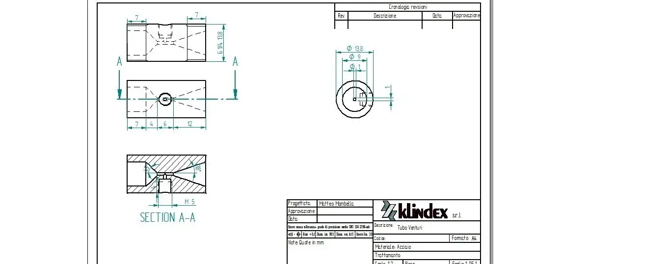
I apologized I imposed 0.5 pressure bar... and found a diameter of 1.2 mm in the restricted section... and during the construction of the piece I made the component realize with a diameter of 1 mm
 
I apologized I imposed 0.5 pressure bar... and found a diameter of 1.2 mm in the restricted section... and during the construction of the piece I made the component realize with a diameter of 1 mm
How come?
making the smaller diameter you have to impose even more depression.
 
How come?
making the smaller diameter you have to impose even more depression.
I did so to make "proof", moreover having hypothesized that the fluid was ideal, absence of losses etc., I seemed lawful to do so and then maybe to enlarge it.

also in the section where I made this 1mm hole I made a channel(detergent) that merged with the steam passage always with a diameter of 1mm
 
I did so to make "proof", moreover having hypothesized that the fluid was ideal, absence of losses etc., I seemed lawful to do so and then maybe to enlarge it.

also in the section where I made this 1mm hole I made a channel(detergent) that merged with the steam passage always with a diameter of 1mm
then I would need you to post a detailed scheme with the measures you actually used.
 
Bye to all,
I am sizing a venturi tube to realize a depression within the boiling chamber of a vacuum evaporator. therefore the fluid is water.
what effects can have the different temperature between suction fluid and exhaust tank? in detail if what I have downstream of the venturi has a temperature higher than the fluid aspirated through the venturi this can lead to suction problems? delta t is contained, we talk about 5-10 °C
 
Hello kariush,
I honestly don't understand your problem well.
the aspiration occurs thanks to the depression generated in the divergent convergent.

the delta t changes the density, therefore the load losses.
 
Hello kariush,
I honestly don't understand your problem well.
the aspiration occurs thanks to the depression generated in the divergent convergent.

the delta t changes the density, therefore the load losses.
Maybe I explained badly. In fact, I happen that the venturi instead of aspiring from the side tube pumps me water. can this phenomenon be attributable to a temperature difference between the mountain and the water valley or to the fact that the pump that circulates the water is undersized for that particular venturi?
Thank you.
 
Maybe I explained badly. In fact, I happen that the venturi instead of aspiring from the side tube pumps me water. can this phenomenon be attributable to a temperature difference between the mountain and the water valley or to the fact that the pump that circulates the water is undersized for that particular venturi?
Thank you.
you have the same mambo problem: the downstream load losses will wipe out the depression in the suction zone. the fluid tends to go away through the venturi instead of "drawing" the other fluid.

Did you put any non-return valves?
 

Forum statistics

Threads
44,997
Messages
339,767
Members
4
Latest member
ibt

Members online

No members online now.
Back
Top