marcofa
Guest
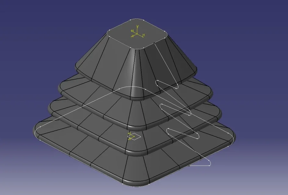
I have to model a rubber bellows as a photo attached.
If it were conical there would be no problem, I made it very easily: profile>> tree
because it is rectangular I couldn't get a spider out of the hole.
I tried with coast but the rectangular director must be squared without rounding and interrupted to get the splash in the photo
thanks for a help
Mar


") )))))))))
)))))))))