• This forum is the machine-generated translation of www.cad3d.it/forum1 - the Italian design community. Several terms are not translated correctly.

maneuver screw

  • Thread starter Thread starter andrea1974
  • Start date Start date

andrea1974

Guest
Hi guys, I have a strong doubt that it can be interesting to define. . . .
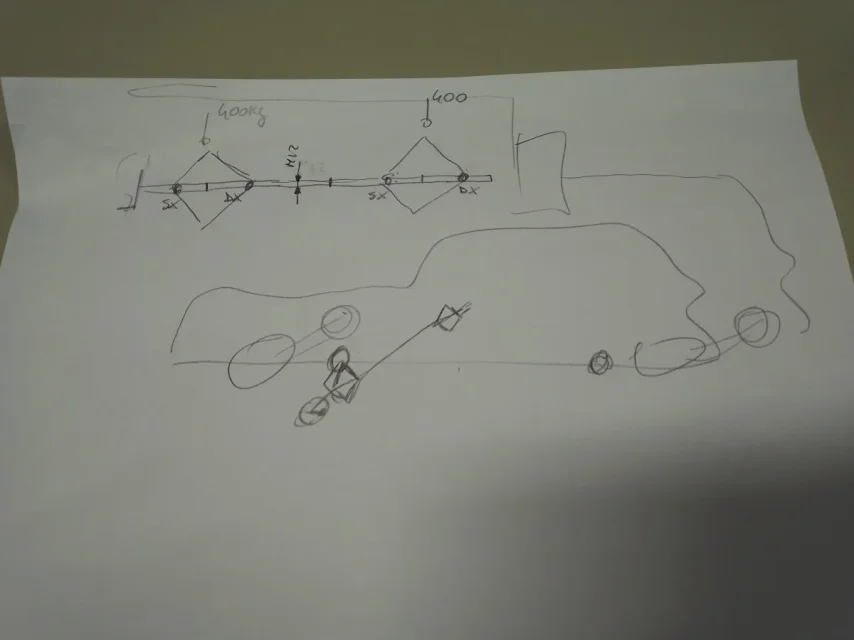
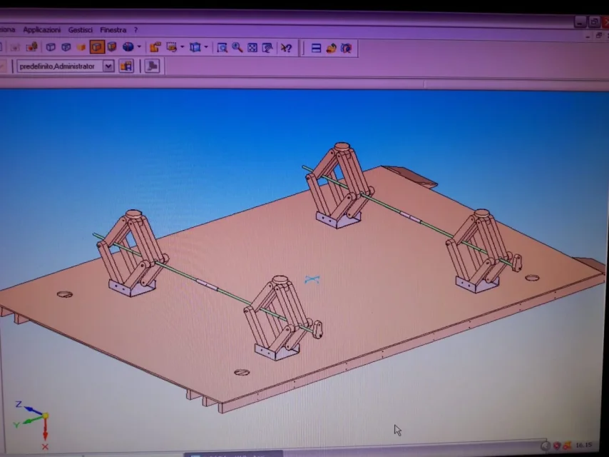
I should build a double-rombo car lift connected in series each of which has to raise we put 400 kg. will be connected by a screw of maneuver, I thought a threaded bar from m12 or higher I don't know yet. .
the question is, can I use a threaded bar that will be built then right and left or do I have to forge to use a trapeze screw? (which costs much more) I don't care about games and precision because the structure that lies outside is basically a crick for cars.. .
 

Attachments

  • IMG_20230213_150800.webp
    IMG_20230213_150800.webp
    23.2 KB · Views: 76
I don't think so. because trapeze screws are made especially for transmission (they have the most thick teeth compared to those of whitworth fillets, iso, etcc...). I'm probably wrong.
 
but my doubt is not that I keep the weight... a screw m12 holds traction about 4800 kg... here the weight is 10 times less, so I don't think it breaks, but rather it nails everything and no more turns anything causes the frictions too high...
 
I would say that first you need to have a minimum of knowledge of building science before building anything that can cause harm to people or things.
other thing you can do, banally it is comparison with a series crick.
Further, a metric screw has little play but does not arise to convey strength as a screw of maneuver. to do this they adopt trapezoidal screws.
nothing prohibits, if evaluated traction/compression efforts and any peak loads you can use a large or fine metric screw.
as in all applications that have a number of drives or relative speeds with appreciable loads, it is blessed to have a steel screw and a bronze / brass nut.
once the two pantographs are made, it is not said that you cannot join the screws of maneuver with a smooth bar in c45.
for whatever you do.
 
I have a minimum of knowledge in construction, I have to better control the serial crick that I think has a simple m12 but I don't know the step though... I have to look
the screws trapezie ok but also needs 8 kilos... in the case, in fact I wanted to avoid

".... once the two pantographs are made it is not said that you can not join the screws of maneuver with a smooth bar in c45...." and what changes? I don't know what you mean. .
I mean you don't have to take 4m of threaded bar. you can decide to use a screw of an appropriate diameter and a smaller maneuver bar.
 
In my opinion the trapezoid screws should be connected through a sleeve left free to slide on one side, as the screws will laterally move, when the lifting is performed.
Secondly, perhaps it is better to put supports on such sleeve, in order to avoid impurities.

p.s. why did you take the axial action on the screw equal to the raised weight? I did not make the balance to the translation of knots but it does not seem very correct. . .
Because I think the car crick works like that.
 
engine? no engine, the movement is hand-made, just like crick for the car, identical.
 
the question is, can I use a threaded bar that will be built then right and left or do I have to forge to use a trapeze screw? (which costs much more) I don't care about games and precision because the structure that lies outside is basically a crick for cars.. .
the jack supplied with my car has a threaded bar of m12 for a range of 1500 kg.
is definitely to avoid a single threaded bar as, in addition to the risk of impurities in the case of misalignment, you must consider that the two lifters would have a fixed distance suitable only for a specific model of car.
as they have already suggested, it is preferable to join the two threaded bars, with connecting shaft at the end of which I would apply two giunti a snodo to compensate for the imbalances you inevitably have in positioning.
if you want to make the system adjustable, you can hold the longer threaded bars and join them with a sliding shaft like this, which allows you an excursion to fit multiple car models; in this way simplify the positioning and compensate the disalignments.
for the positioning of the joint must take into account the translation of the threaded bars.
for the drive it would be preferable that at the end of command you obtained a ch17 attack that you can operate with a normal hatch key or, if you prefer, motorize it with an electric screwdriver (or pneumatic) equipped with a ch17 compass.
keep in mind, however, that if the lifting of both front wheels (rear brakes) can create a minimum of instability, the lifting of the rear wheels at the same time cannot be carried out because you cannot lock the two front wheels.
Moreover, from the safety point, it is a device that lends itself only to interventions on the wheels or brakes remaining outside the car's encumbrance by categorically excluding interventions under the vehicle if there are no other safety devices like easels or other.
 
therefore, forgive me,
I have attached a hand-made sketch to show you a scheme made to the flight, in fact I am far ahead with the project...I attach a more recent photo (it is not yet the last), where almost all these issues mentioned above have already been seen. .

.... "as they have already suggested, it is preferable to join the two threaded bars, with connecting shaft at the end."...

I have already put a tube with two right and left welded nuts as a log screw, but good joint, I keep it present.. I didn't think about it.
With regard to the ends I put a flyer and, with regard to the lifting, I raise a little one another to go on equal pairs and solve thus the instability.
I attach more recent files. .
with regard to safety to slip under it, look that it will be very robust because I use in total 32 beams of fir section 5*7 cm... as each robe will consist of 8 beams with iron pins inserted in the wood but with iron compass (I use a tube)
 

Attachments

  • IMG-20230122-WA0023.webp
    IMG-20230122-WA0023.webp
    84 KB · Views: 63
the jack supplied with my car has a threaded bar of m12 for a range of 1500 kg.... .
So my jack is this, and it is also from outside measure 12 exact, but what thread is it? Does anyone recognize him? It's not metric for sure, but even trapeze seems...
the step seems to be 1.75.. .
 

Attachments

  • IMG-20230218-WA0003.webp
    IMG-20230218-WA0003.webp
    30.8 KB · Views: 53
I don't know that profile.
if you do not find it equal, for your application I would use screws trapezie manoeuvre in bar obtained by removal or wrinkled; with this solution you would have already available the forms and accessories that can serve you.
 
Yes, but I'd keep it as the last beach because it costs a lot more, while these crick bars are ideal, but unfortunately I don't understand what thread it is, we hope someone knows more. .
 
Yes, but I'd keep it as the last beach because it costs a lot more, while these crick bars are ideal, but unfortunately I don't understand what thread it is, we hope someone knows more. .
As many people have already told you, the solution is to take trapezoidal threaded bars from trade and related screws.
I think if you don't have the financial resources to undertake the construction of equipment, it's better to let it go.
 
from the surface finish that you notice in your image, from the rounding of the thread crest and the wear of the working part, could be a barra in ferro grezzo con filettatura whithworth from 1/2" step 2.1 (uni 2709, See table p. 14).
However I would not work under that car as though the lifts are robust (how much?) there is nothing (it seems) that blocks any lateral or forward swings of the medium that could determine the overthrow or deformation of the jacks.
 
therefore, forgive me,
I have attached a hand-made sketch to show you a scheme made to the flight, in fact I am far ahead with the project...I attach a more recent photo (it is not yet the last), where almost all these issues mentioned above have already been seen. .

.... "as they have already suggested, it is preferable to join the two threaded bars, with connecting shaft at the end."...

I have already put a tube with two right and left welded nuts as a log screw, but good joint, I keep it present.. I didn't think about it.
With regard to the ends I put a flyer and, with regard to the lifting, I raise a little one another to go on equal pairs and solve thus the instability.
I attach more recent files. .
with regard to safety to slip under it, look that it will be very robust because I use in total 32 beams of fir section 5*7 cm... as each robe will consist of 8 beams with iron pins inserted in the wood but with iron compass (I use a tube)
It seems dangerous to me to use fir beams to make a lifting device, you say it will be very robust, but how do you verify it, what guarantees do you have?
 

Forum statistics

Threads
44,997
Messages
339,767
Members
4
Latest member
ibt

Members online

No members online now.
Back
Top