• This forum is the machine-generated translation of www.cad3d.it/forum1 - the Italian design community. Several terms are not translated correctly.

technical design

fg_ing

Guest
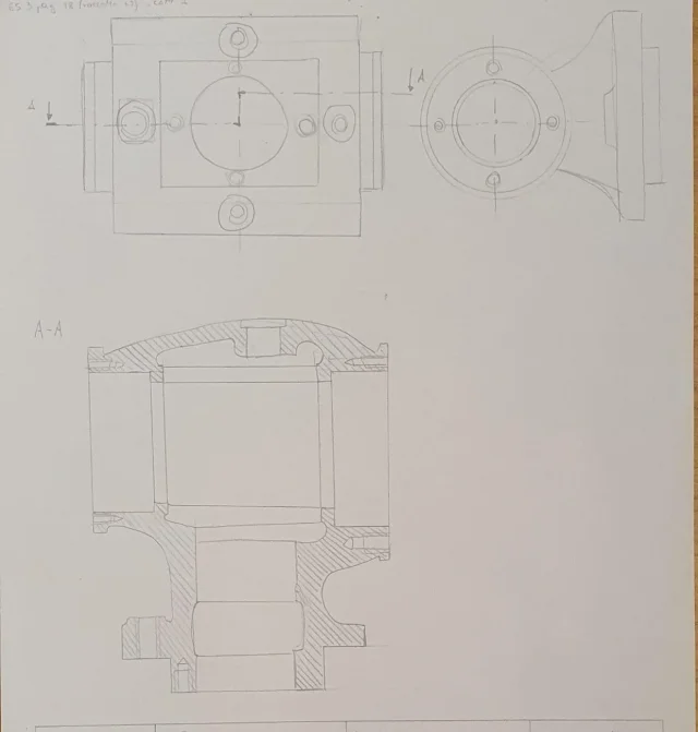
Good morning, I'm new on this forum. I am an industrial engineering student and I am preparing the technical drawing exam. I would like to ask you an opinion on this sketch that I have realized having only the axieme (of a vertical head for milling machine) dissected in attachment. the component I made is number 1. In particular, I am not very convinced of the sectional plan I used but in order to use the date section I did not have any other ideas. I also ask if the view is correct.
I know that proportions are not very suitable. thanks to who can help me
 

Attachments

in principle the section is correct even if the 3 horizontal lines at the center of the body do not go there.
with regard to the other 2 views are personal interpretations not merely references in the starting track.
the section line is wrong because it would mean that the bearing seats are not aligned.
 
In fact, as I said the sectional plan didn't come back. However, if you want to use the date section, where you can see that the screws are arranged in a different way between the right and the left, I have to hypothesize of the mounting screws arranged differently then?
for example 3 screws arranged in triangle?
 
these that I have highlighted if I am not mistaken are mounting screws and for the hypothesis that I did if I made a horizontal and unique section plan they would see from both sides. does it mean that I have to change the layout of the screws rather than the sectional plan?
 

Attachments

  • 1625132760696.webp
    1625132760696.webp
    67.6 KB · Views: 84
Okay, now I know what you're talking about. probably it is 6 screws that being arranged at 60° are visible only on one side. so that base you designed as a rectangle will most likely be a cylinder
 
well, the base could be a cylinder but the problem that arranged at 60° would come as in figure if on one side you have to see. Excuse me if I insist
 

Attachments

  • 1625135575642.webp
    1625135575642.webp
    24.4 KB · Views: 59
in fact I wrote a cagata; should be odd then 5 or 7 or 9....
However, the design in component 2 shows the opening so it is likely that in component 1 it is a false section.
it should also be said that it is not normal screws, but of screws with a square head which are usually used in the groove of the machine tools that cannot be round holes, pertante c'è to wonder if this groove is circular allowing the component 2 (and its components) to be rotated or it is llinear grooves that allow the translation of component 2; In the first case it would not be a false section, while in the second it would be a false section.
is a design that with the only section leaves margins of interpretation
 
just to clarify the concept of grooves
 

Attachments

  • Immagine.webp
    Immagine.webp
    28.8 KB · Views: 45
Now it's clear to me. I was actually wondering how to connect the two components with normal screws. thank you very much for patience and clarification
 
these that I have highlighted if I am not mistaken are mounting screws and for the hypothesis that I did if I made a horizontal and unique section plan they would see from both sides. does it mean that I have to change the layout of the screws rather than the sectional plan?
Good morning I am new to the forum you could have the corresponding legend of the drawing numbers thanks
 

Attachments

  • 1625132760696.webp
    1625132760696.webp
    53.1 KB · Views: 30
I think that the legend has it who posted the design, a good exercise would also be to understand the individual details and give it a name. depends on what you're looking for.
 
to understand the design well, you should rotate the total of 90° to the right, in its normal working position.
so you would see the vertical rod with lower conical part to accommodate the tool and, to left the circular crown with t groove to allow the head to rotate, not to translate.
then, even if it is a sketch, you have made the lines so thin that you do not even see the axes, which are fundamental.
Sorry but I think the request was simply to get the distinct components, of course I refer to post n° 11! The other posts are 3 years ago.
 
Sorry but I think the request was simply to get the distinct components, of course I refer to post n° 11! The other posts are 3 years ago.
My observations are always valid and confirmed.
But if everything had been clarified, why go back on it?
Obviously it has not been and still lacks clarity.
 
My observations are always valid and confirmed.
But if everything had been clarified, why go back on it?
Obviously it has not been and still lacks clarity.
I'm sorry, Marco, the first three-year request phase seems to me to have been clarified, today was formulated another one that has nothing to do with the previous one, so it seems right, if possible, to respond to the latter, correct me if I'm wrong.
 
This is a special combined reducer consisting of an angle reference ratio 1/1 applied to a reducer, represented partially, of which you see only the entry cover and the pair of gears before reduction.
the postponement has a tree connected to the gearing of the reducer and another tree where on one side has a conical attack (cable) and on the opposite side a framework cod for a possible manual drive (made in phase? adjustment?); I don't know the application.
I attach the image on which I reported the designation of the non-normalized construction components; I think you have no difficulty recognizing them.
the terminology I used is not standard, so various manufacturers call components with the same function with different names (e.g. case, body, carcass, etc.), so you have a margin in designation that allows you to name different components, e.g. output support. input shaft, seal ring cover, etc., without invalidating recognition as for each component there is the unique numerical reference.
 

Attachments

  • Rinvio angolare.webp
    Rinvio angolare.webp
    108.8 KB · Views: 35

Forum statistics

Threads
44,997
Messages
339,767
Members
4
Latest member
ibt

Members online

No members online now.
ciao
Back
Top