• This forum is the machine-generated translation of www.cad3d.it/forum1 - the Italian design community. Several terms are not translated correctly.

test tensile strength on cast iron screws g25

  • Thread starter Thread starter easymec
  • Start date Start date

easymec

Guest
Good morning, I have my problem:
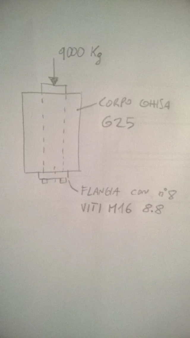
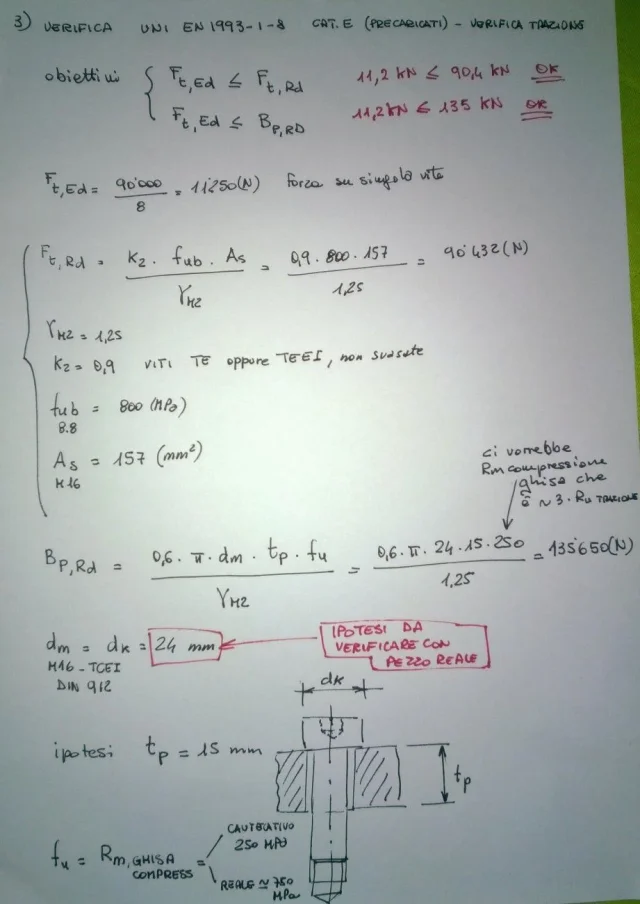
I would like to perform traction verification of the screws / screws fixing of a flange, which are fixed on a g25 cast iron block.
assuming that there is a 9000 kg thrust on the flange.
the first obstacle to me is the fact that I cannot find the yielding load of the g25 lamellar cast iron.
 
for calculation of resistance screws and screws, I recommend looking for my post qui. As for the cast iron does not behave symmetrically between traction and compression. the en-gjl-250 cast iron is a gray graphite cast iron and therefore for its crystalline structure to lamella is not suitable for resisting traction. this cast iron resists compression approximately 3 times compared to the traction load. In fact, this cast iron is used for boilers, machine tool bases and for interior of rolling cylinders. Unfortunately of values on rp0,2 there are no because they are afraid to guarantee the values and it stands at 240mpa theorists... see qui. being very fragile the value of rm is about the same as rp0,2.
 
from another source there are values of resistance characteristics of cast iron g25 or equivalent, according to the regulations. As you can see, the values of rp0,2 may vary quite depending on the casting technology and the very realization of the molten piece. Therefore in a cautionary way, since the yield is almost like breakage, but the deviation of 0.2% is low due to the very steep curve, you should use a value around 150-160mpa.
 

Attachments

  • wp_ss_20180330_0001.webp
    wp_ss_20180330_0001.webp
    19 KB · Views: 97
from another source there are values of resistance characteristics of cast iron g25 or equivalent, according to the regulations.
I thank you for the speed of reply, p
from another source there are values of resistance characteristics of cast iron g25 or equivalent, according to the regulations. As you can see, the values of rp0,2 may vary quite depending on the casting technology and the very realization of the molten piece.
from another source there are values of resistance characteristics of cast iron g25 or equivalent, according to the regulations. As you can see, the values of rp0,2 may vary quite depending on the casting technology and the very realization of the molten piece. Therefore in a cautionary way, since the yield is almost like breakage, but the deviation of 0.2% is low due to the very steep curve, you should use a value around 150-160mpa.
thanks for the prompt response. Could you be so kind to resolve the verification with the data listed above? so be sure to have followed his reasoning. By reading the messages you have proposed, I have a lot of doubts, the verification should be cut or bending as the Malavasi manual indicates?
in the sheet inserted by her for the calculation of the length of the thread, the formula at the bottom right: sigma= sigma s / n (formula for verification), the symbol n to what it refers to? Thank you.
 

Attachments

  • WP_20180330_22_45_06_Pro.webp
    WP_20180330_22_45_06_Pro.webp
    55.8 KB · Views: 137
  • wp_ss_20180330_0002.webp
    wp_ss_20180330_0002.webp
    73.3 KB · Views: 165
so first I would verify the deep discourse to ensure as threads in socket between screws and screws in cast iron.
l > 0.47 • d • rs,max/rs,min = 32 mm per ogni fast da m16if this is guaranteed I would pass to verify according to eurocode 3 uni en iso 1993-1-8 the ability to hold the screw and especially if its lock previews or not the preload, because it is clear that a screw preloaded to 80% has only 20% to carry the external load, while a screw closed with the fingers has 100% capacity to hold the load.

other verification that you can do is see the maximum load of the screw with the yield load declared by the builders
f = 9000kg : 8 = 1125kg
fv = 2920kg screw 8.8 m16 as breaking load
in lifting systems the oversized factor must be 5...and here we are about 2.....acceptable for a standard application where no particular things are required or risks too big and without preload or however with controlled preload.
I checked the hoepli mechanics manual and breaking values for the en-gjl-250 cast iron are based on the thickness, so the breaking load would be 155 mpa (butter). I'm sorry for my ignorance, but does she check her cut and traction on her mothervite? I do not understand where you used the formulas written by you (see previous attachment). This is the part I would like to see resolved, if it is not a problem. My criticality is the mother-in-law if I understand correctly.
 
to tell the truth I made the calculation of the ability of the fillets to resist using the formulas in the post mentioned by me and you attached image. I didn't make traction check according to norm, that I would let her do to you. There's nothing to cut because it's pure traction. the values of rs,min I used cast iron at 150mpa and rs,max that of the screw 640mpa. then last I looked at the tables of the screws, where there are the breaking loads to traction and with that I quickly compared the 9000kg divided number screws. However to do the verification correctly you need to know the field of application of that object, static and/or dynamic stresses, if the screws are preloaded.. .not preloaded....closed to death
 
so to check the threads of the mothervite just use the first formula? because reading in the forum I came across: "the verification to do on the threads is not as much to cut but as to bending, then consider the thread as a beam with force applied to half thread. . . "
always in your formulas, in the lower right sigma = sigma sn / n (check), letter n refers to the safety coefficient?

I ask you to proceed with the verification, as with the values the formulas and the procedure are more clear.We want a static load and that the screws have an average preload.
Thank you.
 
n is the safety coefficient. in our case we considered the report of pure yields. As soon as I have a moment I write everything in full and hoping for good and long thread is verified.
 
I've been doing all my hands to prove to you, since I think you've been in charge of showing that it's resisting but you don't know where to start. I suggest you read at least the 1993-1-8 en iso to understand why formulas otherwise I should stretch a lot and I don't know what you know and what not. So first ask me the things that don't come back.
 

Attachments

  • WP_20180331_16_00_25_Pro.webp
    WP_20180331_16_00_25_Pro.webp
    88.9 KB · Views: 189
  • WP_20180331_16_00_43_Pro.webp
    WP_20180331_16_00_43_Pro.webp
    84.3 KB · Views: 169
  • WP_20180331_16_00_58_Pro.webp
    WP_20180331_16_00_58_Pro.webp
    89.2 KB · Views: 160
  • WP_20180331_16_25_37_Pro.webp
    WP_20180331_16_25_37_Pro.webp
    104.4 KB · Views: 159
Good evening, sorry for my absence. in these days I see the calculations and in case I ask you the perplexity. I think they don't break because it's a 2000 application, but I wanted to understand the calculations/verifies behind us.
Thanks again.
 
the reaction force available to the break is inclusive of preload and load.
If you're charged at 70%, apply us to an equal force and arrive at 0%. 30% more the screw is separated from the piece. after the riot between yielding and breaking....track.
 
the reaction force available to the break is inclusive of preload and load.
If you're charged at 70%, apply us to an equal force and arrive at 0%. 30% more the screw is separated from the piece. after the riot between yielding and breaking....track.
so it is not to be added. How come in the exercise above in the last page point 4 was added effort and precarious?
 
In the sense, I do not have to verify that the sum of the spout and of the precarious force is less than the last resistance of the screw, it is enough that the only traction force given by the load is less than that of the last resistance of the screw?
 
Basically if the screw breaks at 100 you can attack 70+30. otherwise if more breaks.
Of course, if it is preloaded 70... and it applies contrary force of 70 arrives to download the precarious... Then if you apply 30 six to the limit.
is a reasoning that we have made several times about the sliding of the plates.
verification was made in accordance with 1993-1-8.
Screenshot_20240830_152810_Drive.webpas you say: It is enough that the only traction force given by the load is less than that of last resistance of the screw.
 
Thank you so much! If the screw breaks at 100 and the preload at 70, if I apply a force of 70 I go to zero.
from my zero I have available all 100 again before the break right?
 

Forum statistics

Threads
44,997
Messages
339,767
Members
4
Latest member
ibt

Members online

No members online now.
Back
Top