valeria_emme
Guest
I attach a fast file in paitthe blue point, as you call it, is present on the function odds
as you obviously have the instant3d option activated (see help).
you have only one share with two points,the 84 share of sketch1 That's it.
because the sketch is symmetrical.
 ... don't preach to me for using a little orthodox system:biggrin:
I put it, but it doesn't turn black... If I try to define the sketch in an automatic way I see the quota between the point of tangence and the origin, but I do not care... I care that the base is 72, in symmetrical position compared to 84 (i.e. 6 on one side and 6 on the other), that the axis of the cylinder is 130 on the ground, and that the two oblique sides are tangent with the cylinder.. .sketch3 underdefinite, select the two vertices and give the report
horizontality you will see that the sketch becomes black
I know I should do the tutorials, but I'm not well... I do everything with the online guide, don't I? ? ?I strongly recommend you to perform the tutorials.

 but there is only one quota from 84
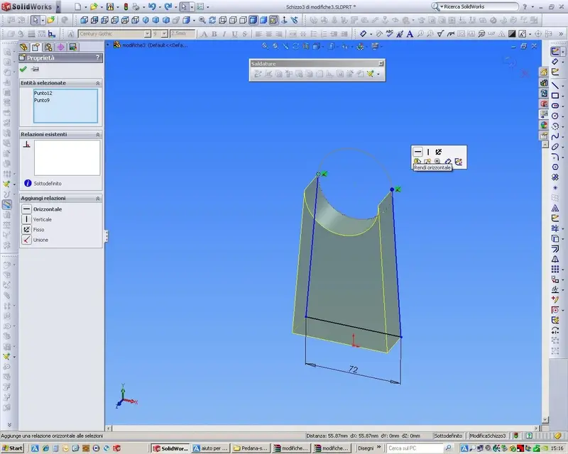

 tongue