feurich
Guest
Hello everyone!
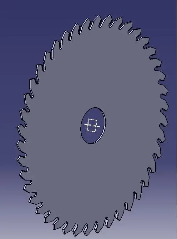
I am working on a project that I need to create as a circular saw but with the teeth bent.
http://www.professionalferramenta.it/19734-42875-large/disco-x-sega-circolare-d.jpgonce designed on a single floor, create a pocket to make the tooth and then apply a complete crown rotation matrix to form all teeth, how can I bend the teeth?

") if you need anything to contact me in my little one I can be useful to you.... good luck for your project....
if you need anything to contact me in my little one I can be useful to you.... good luck for your project....