• This forum is the machine-generated translation of www.cad3d.it/forum1 - the Italian design community. Several terms are not translated correctly.

brushed swivel fin

  • Thread starter Thread starter MaiMollare
  • Start date Start date

MaiMollare

Guest
Good morning
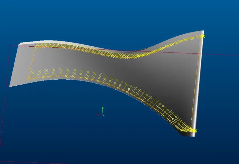
I created a fin of a impeller using the surfaces and the limit blend command using as the spline ends. see (see Figure 2)
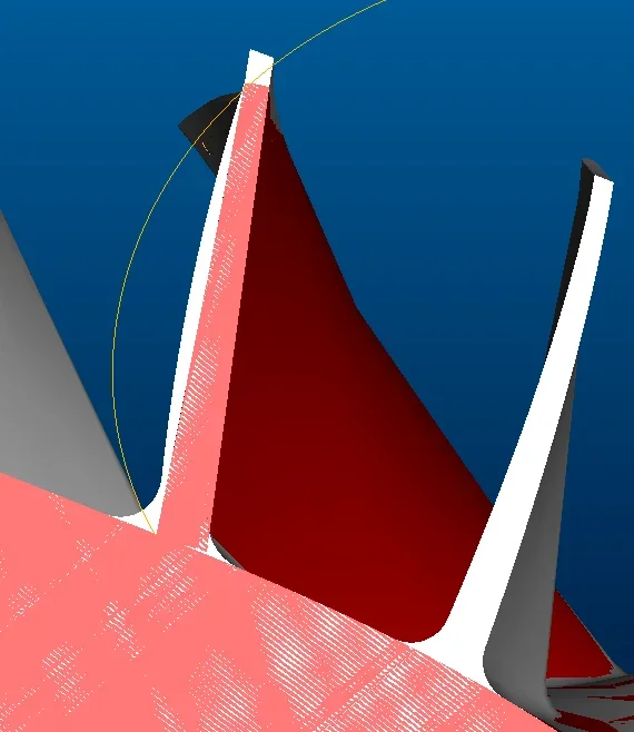
but when I create the aletta and overlap it to another properly executed fin (red aletta figure 1) I see that my gray aletta scatters a lot of vesus the outside, I speak of at least 3mm. My overseas colleagues tell me it depends on the interpolation of the splines, can anyone confirm it?. is there any way to reduce this difference? My American colleagues reduce interpolation by adding limit lines (figure 3).
Is there an alternative solution?
thanks for the help
 

Attachments

  • 1.webp
    1.webp
    35.2 KB · Views: 15
  • 2.webp
    2.webp
    18 KB · Views: 14
  • 3.webp
    3.webp
    83.3 KB · Views: 14
It obviously depends on the splines, since you generated the surfaces from these.
you have to verify that the splines have the right shape and that they are in sufficient number to correctly define the geometry.

without seeing the 3d of the piece, and the splines you used it is difficult to provide you with a correct solution.
 
hello maxopus thanks for the help
In the beginning they give me files with the points in the space through which I pass my splines, so as to have 2 horizontal splines and 2 vertical splines joined together at the top.
I create every face of the aletta with the surfaces with the limit blend command, then the clay and then solidify the aletta.
the spline I use and a spline passing for points see figure.
I hope I've been clear.
Hi.
 

Attachments

  • 4.webp
    4.webp
    33.1 KB · Views: 15
the differences known on the contour (according to the splines) or on the internal zones of geometry?
if the differences are on the contour obviously the position of the points is not correct.
If the differences are on the inner parts of the surfaces, you will need to insert internal guide curves to better define them.
 
Unfortunately the problem is on the internal area of geometry, I was hoping for an alternative solution but I actually expected that it was not possible to do otherwise
Thank you
 
Unfortunately the problem is on the internal area of geometry, I was hoping for an alternative solution but I actually expected that it was not possible to do otherwise
Thank you
that I know the limit blend is controlled only by curves (limits or internal of influence).
I think they are not manipulative like rex surfaces (reverse) for which you can edit the individual nodes that make them.
 

Forum statistics

Threads
44,997
Messages
339,767
Members
4
Latest member
ibt

Members online

No members online now.
Back
Top