• This forum is the machine-generated translation of www.cad3d.it/forum1 - the Italian design community. Several terms are not translated correctly.

centering holes with trolley lift

  • Thread starter Thread starter Hope1
  • Start date Start date

Hope1

Guest
Good morning to all,

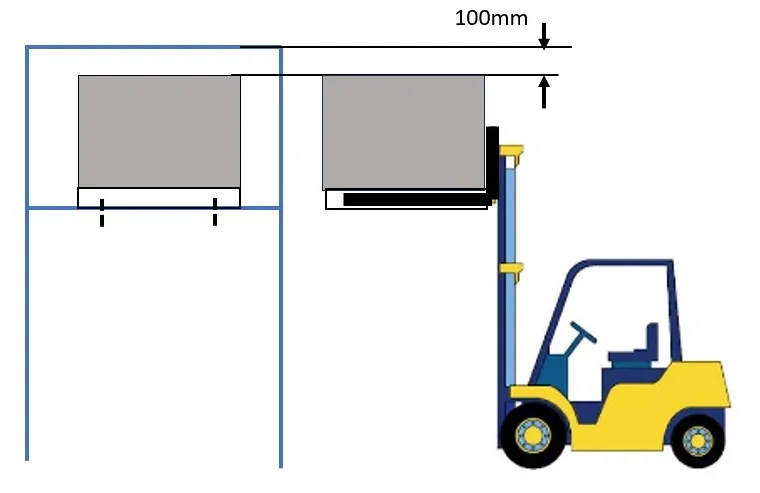
I have a compressor of about 400kg which for reasons of space can be lifted only with a forklift, but I have a doubt. How do I hit the bolt holes since the movimentation is imprecise? Once you lean on the platform it should not be too difficult to push it into "manually" position, but I ask you if there is a more professional way for this kind of installation.

I was thinking of inserting two screws on the compressor support bracket for mechanical adjustment, but every suggestion is well accepted.

thanks also only for reading the message.
 
if you have to move it to center the compressor fixing holes compared to the holes on the (presumption) supporting metal structure once you have supported it (I understand well?), and above all it is a job that you have to do one tantum, you could use a simple lever (if long enough you can generate a non-insensitive force).

in case on the support structure there were no holes, edges etc to be exploited to make the lever work, once supported you could download most of the compressor weight through the bedside (maybe from above with a lifting balance, have space?) so that the weight to move (and crawl on the structure) is no more than 400kg but mooolto less, just the least because it does not move alone.

otherwise welded on the perimeter of the structure of the nuts m24/m40/m...., and with bolts of equal diameter and a key / screwdriver push the compressor in the final position ( compressor/structure holes aligned).
 
I'll tell you how I'd do it.
lifting with bands (no chains).
if the holes on the fixing plate are not threaded you can use two bar discs with a diameter of less than a few millimeters than the compressor fixing holes and 50-60 cm long.
Approach one of the compressor holes as much as possible to the corresponding fixing hole by lowering the compressor at a distance from the floor of about 20 cm.
thread the bar into the hole of the compressor base by getting it out below and going to look for the corresponding hole; having a lot of game allows you some cm swings by facilitating alignment with the hole below. by then lever you can put it completely into the hole of the base and to align the two holes.
lower the compressor a few cm from the plate and with the other round bars, always making a bit of lever, the two holes diagonally opposite, at this point you drop the compressor and levering with the two bars carry out the small movements, sliding the compressor on the base, moving that you need for a more precise alignment of the holes.
now fix the screws in the two diagonally opposite free holes, remove the bars and apply the other two screws.
if the base holes are threaded you need to use brass or copper bars.
Careful! carefully check that operators keep their hands and feet away from the two floors that will be joined.
 
Now you should see a design completely, but you could try to build some sorts of sheet metal guides and weld them to the platform so that the centering is facilitated. allego sample files. Obviously one for each hole or bolt fixing when placing the compressor with the bedbed, should slip on those lips of sloping sheet and center.
 

Attachments

  • lamiera.webp
    lamiera.webp
    23.2 KB · Views: 15
thanks to all for the help, you have understood perfectly the problem but for clarity I have attached anyway the "scheme". 400kg friction factor 0.2 give 80kg in shrinkage that are however many and you are right, I must definitely weld some mechanical help on the base of the compressor to lever.

I was thinking about something similar to the adjustment system that I attached, but I would need it with the longer threaded part. Do you think I'm having too much trouble?

I like the ideas you have proposed:
@terastore e @ragnol, unfortunately I have practically no space over the compressor.
@infallible_gf, the welded sheet guide would help safely and I will keep it in consideration for future installations - unfortunately in this case if I use it I should lift the compressor more ' and the 100mm gap would be reduced.

Fortunately the assembly/disassembly takes place only once a year. I also put another question: but according to you the 100mm are acetable as a space for a forklift?
 

Attachments

  • sollevamento .webp
    sollevamento .webp
    9.4 KB · Views: 12
  • regolazione posizione.webp
    regolazione posizione.webp
    8.4 KB · Views: 11
Have you ever used these screws? I could put one close to each side by screwing it from below to lift the compressor. If the ball at the top really rotates, it should be very simple to move even by hand.
 

Attachments

  • Ball ended thrust screw.webp
    Ball ended thrust screw.webp
    10.2 KB · Views: 9
Have you ever used these screws? I could put one close to each side by screwing it from below to lift the compressor. If the ball at the top really rotates, it should be very simple to move even by hand.
no excuse, I wrote a chestnut - those screws are used to obtain a controlled reaction force on the tip, regardless of the tightening of the screw.
 
from my experience on the yards considering that the trucker does not see the upper part of the machine to be positioned must be made by force to help from a colleague who has another angle of view, because 100mm are really few.
But it seems to me to understand that everything is already existing so 100mm are and remain.
 
comunque le guide proposte da @infallible_gf they can help you a lot if you only mount from the back to have a certain positioning and a mechanical joke.
In this way you don't need to raise a lot, just tap the shelf and then go to a bar with a drill biter centers the holes.
 
in these proposed guides, which are good, if you open beyond 90° the vertical fold, you also have a horizontal translation center, as well as vertical.
 

Forum statistics

Threads
44,997
Messages
339,767
Members
4
Latest member
ibt

Members online

No members online now.
Back
Top