calzand
Guest
Good morning to all,
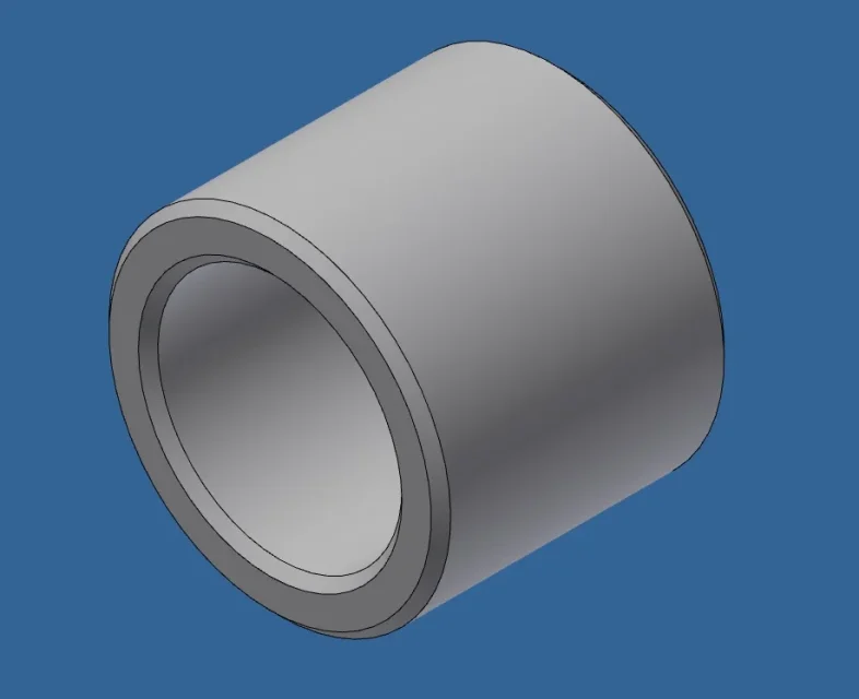
I have a mouthpiece with the bevels at 45°x1 now I have to change it and make the corner connected r1.
this bushing is in many assemblies mounted with pivot/hole bond.
Is there a way to change it without losing constraints in the assemblies?
I have a mouthpiece with the bevels at 45°x1 now I have to change it and make the corner connected r1.
this bushing is in many assemblies mounted with pivot/hole bond.
Is there a way to change it without losing constraints in the assemblies?