Tantocattivo
Guest
Hi.
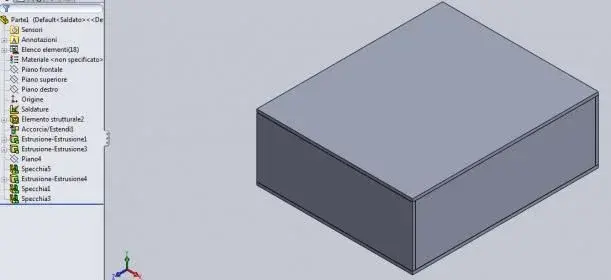
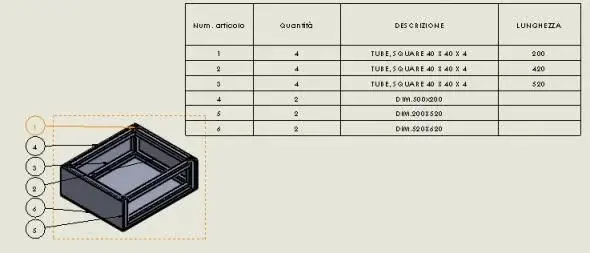
Premitting that I'm self-taught, I've got a problem on the cut-off. I was creating my own profiles by following the advice of http://www.cad3d.it/forum1/showthread.php?t=12698&highlight=distinta+taglio . the distinct comes out with the number of correct pieces, but does not fill me the description and length. I practically correctly see article number and quantity but not description and length. I press one thing, the design is a multibody part made with the struttral member and the rest modeled in the part. for clarity I attach the design in sw 2010.
Thanks
added:
I did a section in a position and I would like to move it exactly on the line of half-carry but does not make me put relationships like coincidence type or a quota equal to zero, so now that the alien section is made, like the exact shifteming on a line?