mob
Guest
Hello everyone
I have a doubt that it's been a long time since... and I try to explain it to you with examples.
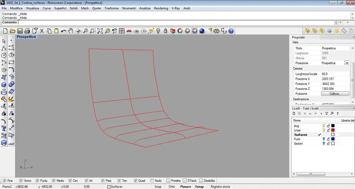
in image 1 you see the sections of a session that I will build with the network command
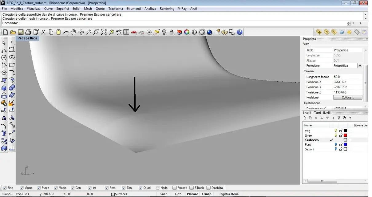
In image 3 (the two does not exist :biggrin") we see a particular of the surface that I obtain that I consider quite smooth and without particular discontinuity.
we see a particular of the surface that I obtain that I consider quite smooth and without particular discontinuity.
in image 4 I went to cut the frontal aprte of the surface and I go to reconstruct it with network command using the same sections first but setting tangence on the side to which is that of the surface.
in image 5 you see the new surface build, while in image 6 there is a first floor of the detail before. nothing clamorous, but you notice a small vein along the edge I used to build and that before, with the network command used throughout the surface, there was no.
Now... I wonder why.... it happened to me a thousand times, with the appearance of veins and hump but more obvious.
often modeling chairs maybe I have to go to change the surface of the seat in particular points, setting additional sections to better address the performance of the seat. So I have to cut them and rebuild them only at that point by hooking me to what remains of the first surface. in any case whether I use network with tangency or curvature set, whether you use a b-rail, whether you use the patch in case of 3 sides, or use other commands and then go to use it combines surfaces and then set the continuity I prefer....the result does not change... .
If I break the surface, this doesn't come back as when I build it with one command.
Is that normal?
solutions?
Thanks milla:finger:
I have a doubt that it's been a long time since... and I try to explain it to you with examples.
in image 1 you see the sections of a session that I will build with the network command
In image 3 (the two does not exist :biggrin
we see a particular of the surface that I obtain that I consider quite smooth and without particular discontinuity.in image 4 I went to cut the frontal aprte of the surface and I go to reconstruct it with network command using the same sections first but setting tangence on the side to which is that of the surface.
in image 5 you see the new surface build, while in image 6 there is a first floor of the detail before. nothing clamorous, but you notice a small vein along the edge I used to build and that before, with the network command used throughout the surface, there was no.
Now... I wonder why.... it happened to me a thousand times, with the appearance of veins and hump but more obvious.
often modeling chairs maybe I have to go to change the surface of the seat in particular points, setting additional sections to better address the performance of the seat. So I have to cut them and rebuild them only at that point by hooking me to what remains of the first surface. in any case whether I use network with tangency or curvature set, whether you use a b-rail, whether you use the patch in case of 3 sides, or use other commands and then go to use it combines surfaces and then set the continuity I prefer....the result does not change... .
If I break the surface, this doesn't come back as when I build it with one command.
Is that normal?
solutions?
Thanks milla:finger: