• This forum is the machine-generated translation of www.cad3d.it/forum1 - the Italian design community. Several terms are not translated correctly.

crankshaft shape for a 4 cylinder motor - 4 times

  • Thread starter Thread starter Paolo Pichierri
  • Start date Start date

Paolo Pichierri

Guest
Good morning to all,
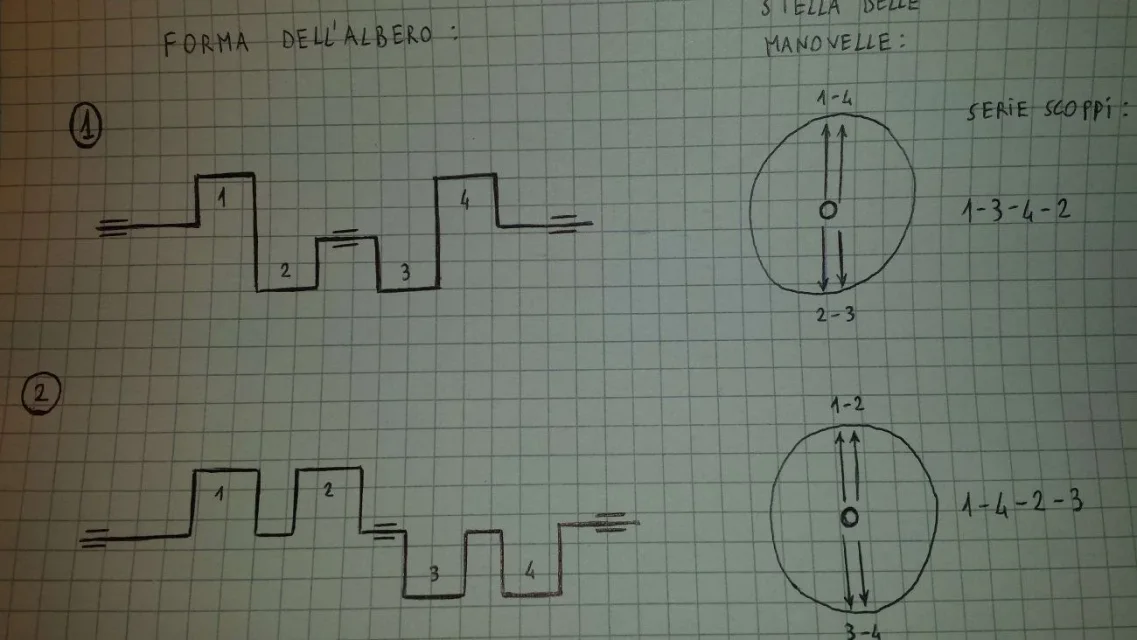
considering a 4-cylinder inline engine - 4 regular break times (one burst every 180°), I wondered why the star of the cranks (i.e. the shape of the shaft) predicts the 1-4 "sphased" cylinders between them of 360° as well as the 2-3 cylinders (case 1, in the attached image). Why would it be wrong to take different configurations? for example 1-2 and 3-4 (case 2, in the attached image). the textbook from which I am studying only mentions as justification "balance of inertial forces". but honestly I'm not able to see what can change between one case and another.
I thank in advance those who can clarify my ideas a bit;)
 

Attachments

  • Albero a gomiti.webp
    Albero a gomiti.webp
    82.4 KB · Views: 21
Last edited:
try to imagine the engine in the release phase (so we don't care about the push, but only the dynamic balance). now remove the two extreme supports of the motor shaft (leaving only the one in the center) and turn it.

in the first case, on the one hand you have a piston that moves in one direction and one in the opposite direction; same situation on the other side. both the amount of motion, and the moment of the amount of motion compared to the pole represented by the central support. the tree is balanced.

In the second case you have that while the two right pistons rise, the two left ones descend. the amount of motion is cancelled as in the other case, but the moment of the amount of motion is now added, bringing the tree to slam at every rotation.

making a tree like the second you drew, the efforts on the side supports would be enormously greater, so... you don't.

if we also consider the ignition sequence, things get complicated, but the juice remains the same: the correct choice is that in the first drawing to reduce vibrations and efforts on the supports.
 
hello paolo,as exxon has already answered, the question concerns the balance at times ..
helps to consider the centrifugal forces that arise during rotation.
a tree is appropriate both:
- Statically balanced when the centre of gravity lies on the rotation axis (practically you notice it because it remains firm if it changes by hand the angle position, once it is placed on the counter supports). theoretically this condition is met by both of your examples.
- dynamically balanced when and the result of the moments generated by centrifugal forces considered compared to any point of the axis is zero (only case 1 meets that condition).

you have noticed that the rule according to which you reach the dynamic balance "without knowing how to read or write" (as my teacher said) provides that the tree is:
1) Statically balanced
2) symmetrical with respect to the rotation axis halfway (the cranks must be symmetric in shape, position and number).

this can happen if they are in equal numbers, if in odd numbers the counterweights are used (as in the case of monocylindrical or bicylinder motor). .

I hope to have been helpful and good study;):giggle:
 

Forum statistics

Threads
44,997
Messages
339,767
Members
4
Latest member
ibt

Members online

No members online now.
Back
Top