• This forum is the machine-generated translation of www.cad3d.it/forum1 - the Italian design community. Several terms are not translated correctly.

curve in space for loft

  • Thread starter Thread starter mario.lamagna
  • Start date Start date

mario.lamagna

Guest
Hi guys, I'm new to the forum; I introduce myself briefly, I'm an engineering student in the second year, a newbie in short.

from a few weeks I've left with solidworks and I'm good enough.

We come to the therefore, I must draw a curve in space (not flat).

In particular, I need to use it as a guideline for a loft extrusion.

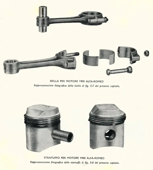
looking at the design you can definitely understand what I'm talking about; it is the connection of the stem of the biella with the head; the view from above indicates a connection of 150 and the side of 100.

first of all I would like to know if my approach is correct; I first extruded the central part of the stem using the two given sections and making a loft. But now I don't know how to take this particular curve to the section. . because it must also enlarge.

how would you realize this piece? the rest of the biella is really trivial, but I miss this step.

I attach the design and views for completeness.

I hope in your help.


thanks in advance
 

Attachments

  • IMG_0001.webp
    IMG_0001.webp
    377.7 KB · Views: 37
  • IMG.webp
    IMG.webp
    347.2 KB · Views: 23
the loft is not necessary. I would do a half or a quarter of the central part shaped with extrusions, cuts, deforms, fittings, etc. as a distinct body and in the end I would mirror this body and go to join others.
 
to get the result you want there are more approaches.
each approach is less performing than the other.
The loft is the worst.
I'll get you an approach.
then you could try with sharing multiple bodies or with replacing the face or with extrusion to the face.
 

Attachments

Hi guys, I'm new to the forum; I introduce myself briefly, I'm an engineering student per second year
(cut)

Let's get to the chase.

(cut)
thanks in advance
I answer briefly only to congratulate you on the ability to explain your problem in a clear, detailed but concise manner. lately this is very rare merchandise... :finger:
Whoever reads you if he doesn't understand the first stroke means he "brained his brain" [cit.] :smile:

all to the first message.. .
newcomers, those to whom we must tear clarifications and images with pliers and for which we need at least 10 posts to frame the problem learn.
 
Thank you for your compliments.

I must inform you that in the end my answer was in the flexo function that I discovered the other last night! !

I extruded the terminal zone of the stem from the part of the head (of course only a half that then went to mirror), making a loft that increased the section in height according to the descriptions of the side projection of the piece; to do this I used a circumference arc of the right radius as a guideline.
then working on the coordinates of the flexo function I managed to bend it correctly, this time with the radius that was indicated in the view from above. In this way I avoided the hated curve in the plan that according to my poor knowledge I couldn't trace. . . mirroring then compared to the front floor the game is made.

Now of course new problems are emerging regarding the development of the piece, but I will try to stem them.
If I have problems I will let you know!! !

I thank you for the advice.
However, for the lines in space 3d, there is 3d sketch.
 

Attachments

  • Cattura.webp
    Cattura.webp
    129.1 KB · Views: 27

Forum statistics

Threads
44,997
Messages
339,767
Members
4
Latest member
ibt

Members online

No members online now.
Back
Top