John
Guest
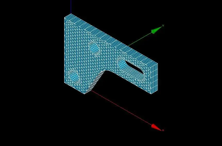
Hello everyone, I wanted to ask for information I have to calculate the pressure before arriving at plastic deformation (yielding point 260mpa) in this piece with the following data:
e = 200 gpa
poison's ratio=0.3
density =7860 kg/m^3
thickness = 10 mm
measurements in mm I created two models one with
solid>quad 8node 82
solidity
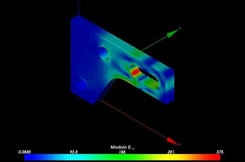
but the results obtained are different
in the first case arrive at 251e6 for a load of 2e7 pa
in the second case I arrive at 278e6 for a load of 2e7 pa
So I have doubts:
If I select different elements I get different results, I mean big differences (about 30 mpa)?
If I intensify mesh in critical points, i.e. in holes and fillet, should results change a lot?
thanks to those who will answer me:biggrin:
e = 200 gpa
poison's ratio=0.3
density =7860 kg/m^3
thickness = 10 mm
measurements in mm
 I created two models one with
solid>quad 8node 82
solidity
but the results obtained are different
in the first case arrive at 251e6 for a load of 2e7 pa
in the second case I arrive at 278e6 for a load of 2e7 pa
So I have doubts:
If I select different elements I get different results, I mean big differences (about 30 mpa)?
If I intensify mesh in critical points, i.e. in holes and fillet, should results change a lot?
thanks to those who will answer me:biggrin: