PaoloMUTZ
Guest
Good morning to all, I am paolo m. and is the first discussion I create even if I have been following for several years cad3d.
I kindly ask you support for the sizing of a hammer mill that was commissioned for the company in which I work.
I do not ask you to solve calculations (as precise data concerning forces/masses/dimensions etc. are not yet known to me) but rather I ask you if possible to illustrate the procedures/forms to be used so as to enact a spreadsheet.
therefore:
I have to dimensional the hammer mill (photo attached), which will take care of chopping electric motors (meaning large like the fist of a hand) and to shreds of electric cables.
the system consists of a central body on which 28 free hammers are mounted (available in 4 rows). the central body rotates on its axis thanks to an electric motor.
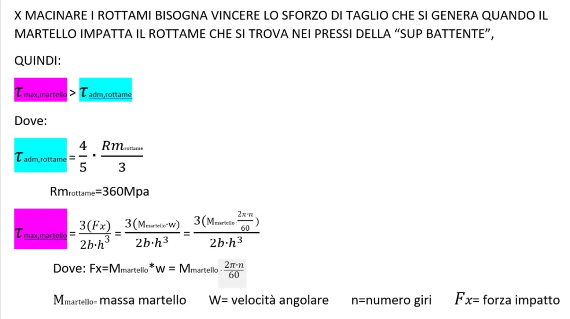
the break of the pieces (electric motors and wires) takes place due to the effect of the cut between the hammer and the flying surface that in the photo is called "sup battente"
what sends me into trouble is how to consider the fact that hammers can rotate freely and then how to consider impacts / impacts / cut forces in play.
Does anyone have any ideas? thank you very much (good to make)
I kindly ask you support for the sizing of a hammer mill that was commissioned for the company in which I work.
I do not ask you to solve calculations (as precise data concerning forces/masses/dimensions etc. are not yet known to me) but rather I ask you if possible to illustrate the procedures/forms to be used so as to enact a spreadsheet.
therefore:
I have to dimensional the hammer mill (photo attached), which will take care of chopping electric motors (meaning large like the fist of a hand) and to shreds of electric cables.
the system consists of a central body on which 28 free hammers are mounted (available in 4 rows). the central body rotates on its axis thanks to an electric motor.
the break of the pieces (electric motors and wires) takes place due to the effect of the cut between the hammer and the flying surface that in the photo is called "sup battente"
what sends me into trouble is how to consider the fact that hammers can rotate freely and then how to consider impacts / impacts / cut forces in play.
Does anyone have any ideas? thank you very much (good to make)