• This forum is the machine-generated translation of www.cad3d.it/forum1 - the Italian design community. Several terms are not translated correctly.

discussion

  • Thread starter Thread starter rizzoliomatteo
  • Start date Start date

rizzoliomatteo

Guest
Good morning, gentlemen.
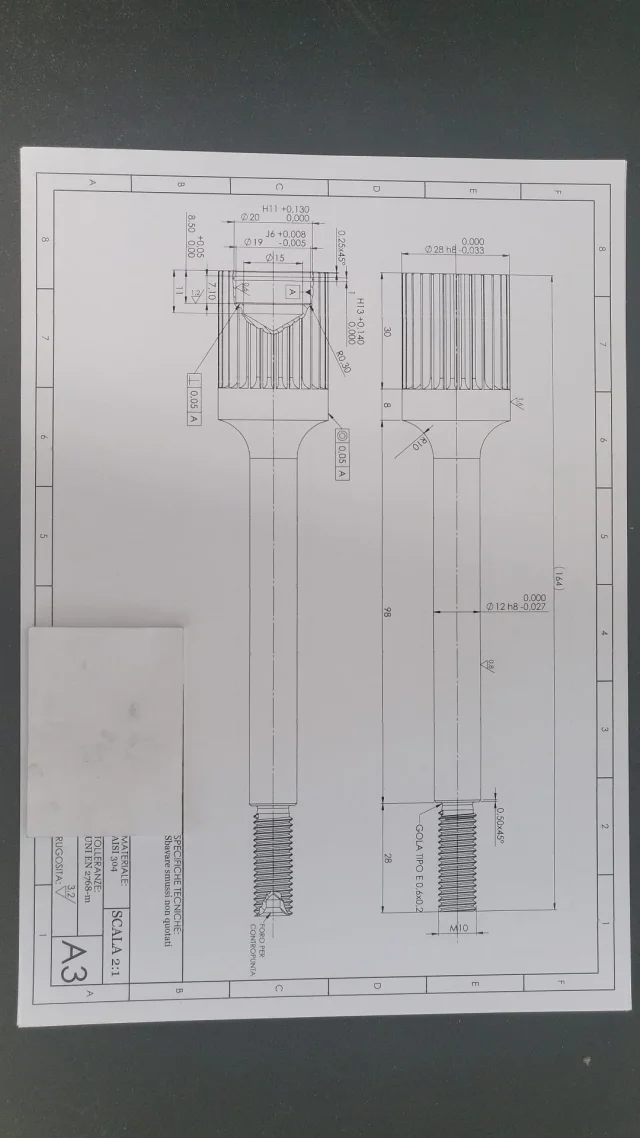
it was my intention to submit a drawing of a tree from me realized, so that you all, having much more knowledge and above all experience of me, can judge and advise me changes and or errors committed.

Thank you in advance for anyone who can help me.

I wish you a serene day
 

Attachments

  • Albero.webp
    Albero.webp
    108.3 KB · Views: 60
as before they never dissect trees like that!! instead of the section do a split where quoti the hole and its tolerances
 
I would have put a positioning tolerance for the seeger throat (7.10 ) I don't see well from the photo, but is there a perpendicularity under roughness 1.2?
If there is (beautiful ignorance I have never seen it quoted so) you have to give it a reference, I imagine it is a reference to the starting face of the thousand lines: in the quotation, as far as possible, you do not have to leave possibility of interpretation to the operator and besides could not be indispensable.. but it depends on what we have to do inside.
to make fleas, for ease of reading, always quota 7.1 would have put it first, not external to all. reading is more immediate if the quota lines do not intersect. .

I strongly advise you to build the thread in 3d.
in addition to taking away a sea of time (not justified for the final result) if that detail goes within a set, it weighs much.
if it is not the only thread but there are others, you become unmanageable the opening and modification of the axieme.

directions for the thousand lines?

so on the fly... :
 
Good morning, gentlemen.
thank you so much for the things
I would have put a positioning tolerance for the seeger throat (7.10 ) I don't see well from the photo, but is there a perpendicularity under roughness 1.2?
If there is (beautiful ignorance I have never seen it quoted so) you have to give it a reference, I imagine it is a reference to the starting face of the thousand lines: in the quotation, as far as possible, you do not have to leave possibility of interpretation to the operator and besides could not be indispensable.. but it depends on what we have to do inside.
to make fleas, for ease of reading, always quota 7.1 would have put it first, not external to all. reading is more immediate if the quota lines do not intersect. .

I strongly advise you to build the thread in 3d.
in addition to taking away a sea of time (not justified for the final result) if that detail goes within a set, it weighs much.
if it is not the only thread but there are others, you become unmanageable the opening and modification of the axieme.

directions for the thousand lines?

so on the fly... :
Good morning dum,
thank you very much for the advice, I immediately remedyed the cutting error of the tree and inserted your shortcomings (I attach new photo)

with regard to the perpendicularity of roughness, and a feature present on solidworks, but are not at all certain delicacies of its rightness,

As regards the quotation of the teeth, it has not been carried out since it will then be realized by a second supplier, to which I will provide indications of the most detailed quotation.

you are right, the 3d thread throws down the power of the pc during the opening phase, but the following component will go to be assembled in a set consisting of few components, therefore the opening of the file will not affect my gpu.

Thank you again and wish you a serene day
 

Attachments

  • Albero.webp
    Albero.webp
    91.5 KB · Views: 48
Hello, always for "pignoleria"1719998298277.webpthe partial section, fall on the whole "red" area, made so small risks making reading quotas difficult.
8.5 frame it between quotas 7.1 and 11, so you won't have quota lines that occur ( cleaner).

perpendicularity I have never seen her quoted so, but net of my ignorance, you have to tell him to what face it has to be perpendicular and from a range of "perpendicularity". .

type
1719998564626.webpIf you don't tell him what it has to be perpendicular, the operator then gets pesky... :)

Have a good day!
 
perpendicularity I have never seen her quoted so, but net of my ignorance, you have to tell him to what face it has to be perpendicular and from a range of "perpendicularity". .
that symbol of perpendicularity refers to roughness and not to the geometry of the particular. the same goes for the "r" under 1.6. It is not that because there is the possibility of inserting letters you have to put them by force without knowing what they serve. . .
the seat of the diameter of the sedger is h12 and not h11

and then leave the symbols of diameter cheerfully. . .
 
Last edited:
that symbol of perpendicularity refers to roughness and not to the geometry of the particular. the same goes for the "r" under 1.6. It is not that because there is the possibility of inserting letters you have to put them by force without knowing what they serve. . .
the seat of the diameter of the sedger is h12 and not h11

and then leave the symbols of diameter cheerfully. . .
good evening massivonweizen,
say well, aim is on my mechanics manual, where I quickly recovered the tolerances, the phi 19 is not reported as a diameter for the sedger.

As for the omission of the diameter symbols I immediately provided, I apologize for the oversight.

However, I do not understand your arrogance in the first statement, I have repeatedly reiterated in this forum my little experience (I am 19 years old) I am convinced that experimenting things, although wrong is part of the normal learning path towards mastery in a given field.

But maybe I'm wrong.

Thanks for the tips and tips, I wish you a serene massive day.
 
that symbol of perpendicularity refers to roughness and not to the geometry of the particular. the same goes for the "r" under 1.6. It is not that because there is the possibility of inserting letters you have to put them by force without knowing what they serve. . .
the seat of the diameter of the sedger is h12 and not h11

and then leave the symbols of diameter cheerfully. . .
Given my mistake, could you explain to me better what the r or all the other symbols is? You seem to be aware of it.
 
for the hole from 19 tables say that the seat has diameter 20 with h12 tolerance; the tolerance h11 is for immediate lower dimensions.
regarding the acerca roughness on the net - wrinkle technical design - and open some pdf, you will surely find those symbols.
If you wanted to put geometry tolerances it seems strange to me that the mechanics manual does not treat the topic of their indication.

both the tolerance of the serger and the symbols of roughness are indicated on the vademecum baldassini.

note in margin:
you can also consider it arrogance, but it remains that in a design every element has meaning that it transmits to those who read it what you want to communicate. that means that behind every element there is a thought and a necessity.
you are at the first weapons with the design so it is normal that you make mistakes, but if the symbol of perpendicularity can be considered a review on the use of geometric tolerance I can not find any motivation to that "r" under 1.6; therefore I wrote that the possibility of inserting information implies having to do it.
I could have observed that the brackets indicate an accessory information (in fact they are used to indicate the non-functional quotas due to a summary), in your case they make sense in the encoded tolerances as subordinate to the class of belonging and serve only as help to the operator, but they should not be placed on unclassified scaffolding.
thanks massive,
I have corrected my mistakes, I attach the modified design with attached geometric tolerances,

As regards the use of brackets, you say well, they are to be used for repeated elements or summaries, I had never thought of it, but our professors all'itis have always made them represent with brackets the deviations.

Thanks again and wish you a good evening.

ps: Please do not contain your laziness, I need to learn as much as possible from you who are more experienced than me.
 

Attachments

  • Albero.webp
    Albero.webp
    126.9 KB · Views: 23
thanks massive,
I have corrected my mistakes, I attach the modified design with attached geometric tolerances,

As regards the use of brackets, you say well, they are to be used for repeated elements or summaries, I had never thought of it, but our professors all'itis have always made them represent with brackets the deviations.

Thanks again and wish you a good evening.

ps: Please do not contain your laziness, I need to learn as much as possible from you who are more experienced than me.
if you want to learn, you must first be positive and do not limit yourself to posting the drawing by asking for corrections and suggestions; What do you want us to know what that component needs?
if it is a fine school design itself should be declared, if it is a design of a component of a assembly it should be explained to what it serves. in any case you must strive to explain your choices.
otherwise all you can do is notice gross errors, shortcomings or unnecessary.
if instead you provide a disamination of the choices you can unfold a really constructive confrontation where you go beyond the right/wrong and also receive explanations on work, functionality, experiences, etc.
For example:
Why did you put a roughness of 0.6 on the hole? You know what it's like and how you get it?
Why did you put a wrinkle of 0.8 on diameter 12? Can you get it while having a final radius?
How does a lathe make to understand what measures to do for "couple hole"?
motivates geometric tolerances
motivates why you haven't changed your tolerance to seeger's seat, because you haven't expanded the decomposed section as written by @dum, because you took the parentheses to the disturbances of tolerances it when I wrote that they were okay.

graphic:
you have made two identical views only to quote the hole in which the odds are sticky; you could do a detail with interrupted section or directly a section enlarge it and better place the quotation.
 
Good evening,
the component in question will be to store bottles, integrated into a set.

As for your technological background questions, I can tell you that the roughness of the hole 0.6 is due to the presence of a bearing, more precisely the 607-2z that requires such small roughness, I know that it will probably not be possible to obtain such a finish with the only turning, and therefore it will be necessary to pass on rectification.
on diameter 12 I have inserted a roughness 0.8 as in that area I will go to shovel of the roller cages to add a bond to the axieme, could you explain why the radius should create problems for the finish?
I do not see reason to quote the hole for the counterpoint, as I am not aware of the tips that will go to use the cnc operator, and however it has been inserted only to recommend to work the piece on counterpoint and not to swing, as I often see doing in the workshop.
geometric tolerances are the classics that taught us at school when we are in front of bearing locations, the approach used is therefore academic, not experience, if you have advice to give me, I am happy to listen to them.

As for the graphics part I have improved the layout by adding a view in detail as you recommended.

I attach photos of the latest version.

thanks again to all and especially to you @massivonweizen
 

Attachments

  • Albero.webp
    Albero.webp
    73.5 KB · Views: 32
As for your technological background questions, I can tell you that the roughness of the hole 0.6 is due to the presence of a bearing, more precisely the 607-2z that requires such small roughness, I know that it will probably not be possible to obtain such a finish with the only turning, and therefore it will be necessary to pass on rectification.
on diameter 12 I have inserted a roughness 0.8 as in that area I will go to shovel of the roller cages to add a bond to the axieme, could you explain why the radius should create problems for the finish?
wrinkles 0,8 and 0.6 are obtained from rectification therefore require an unloading throat for grinding the grinding wheel. with turning you can arrive, with excellent equipment to 1.6...
diameter 15 is not good because it will contact the seal.
to me it turns out that the roughness for an it6 is 0.8, where did you read 0.6? In any case it is rectification and therefore serves drainage throat especially on holes with narrow dimensions.
I do not see reason to quote the hole for the counterpoint, as I am not aware of the tips that will go to use the cnc operator, and however it has been inserted only to recommend to work the piece on counterpoint and not to swing, as I often see doing in the workshop.
if the piece is to be rectified, you need the holes for the counterpoint and these holes you decide them according to the diameter of the shaft. the center holes are standardized and therefore have well defined measures; If the turning pointer is his head and then the piece in the grinding phase does not remain firm or deforms the thread, the fault is yours that you did not give him correct indications. the operator like the editor should not interpret or invent anything and should not replace the designer. check the rules on the manual.
geometric tolerances are the classics that taught us at school when we are in front of bearing locations, the approach used is therefore academic, not experience, if you have advice to give me, I am happy to listen to them.
on holes of so small size where the shouldering is just two millimeters to impose a perpendicularity of 0.05mm is useless because it would mean that during grinding the grinding the grinding the grinding wheel comes out with a strong inclination and it is impossible or however if it happened would be the last of the problems; Moreover it would increase the costs both of processing (more precisely the processing would be the same, but the supplier increases the price by virtue of tolerance) and control.
with regard to concentricity it would be more correct to put it on the teeth and however you are indicating that the rectified diameter 12 does not matter if it is not concentric.
 
a very useful thing would be to go with the drawing from who will work the particular and ask to be explained the procedure of execution.
 

Forum statistics

Threads
44,997
Messages
339,767
Members
4
Latest member
ibt

Members online

No members online now.
Back
Top