• This forum is the machine-generated translation of www.cad3d.it/forum1 - the Italian design community. Several terms are not translated correctly.

dissect an aerophotogrammetry

  • Thread starter Thread starter Brandotw
  • Start date Start date

Brandotw

Guest
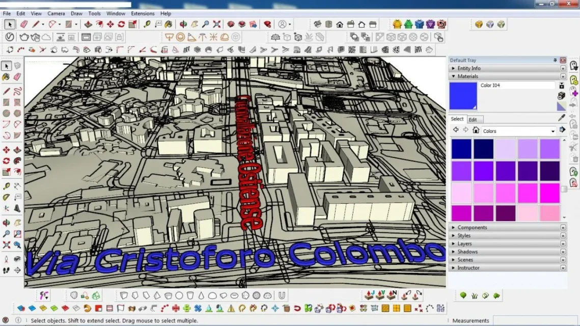
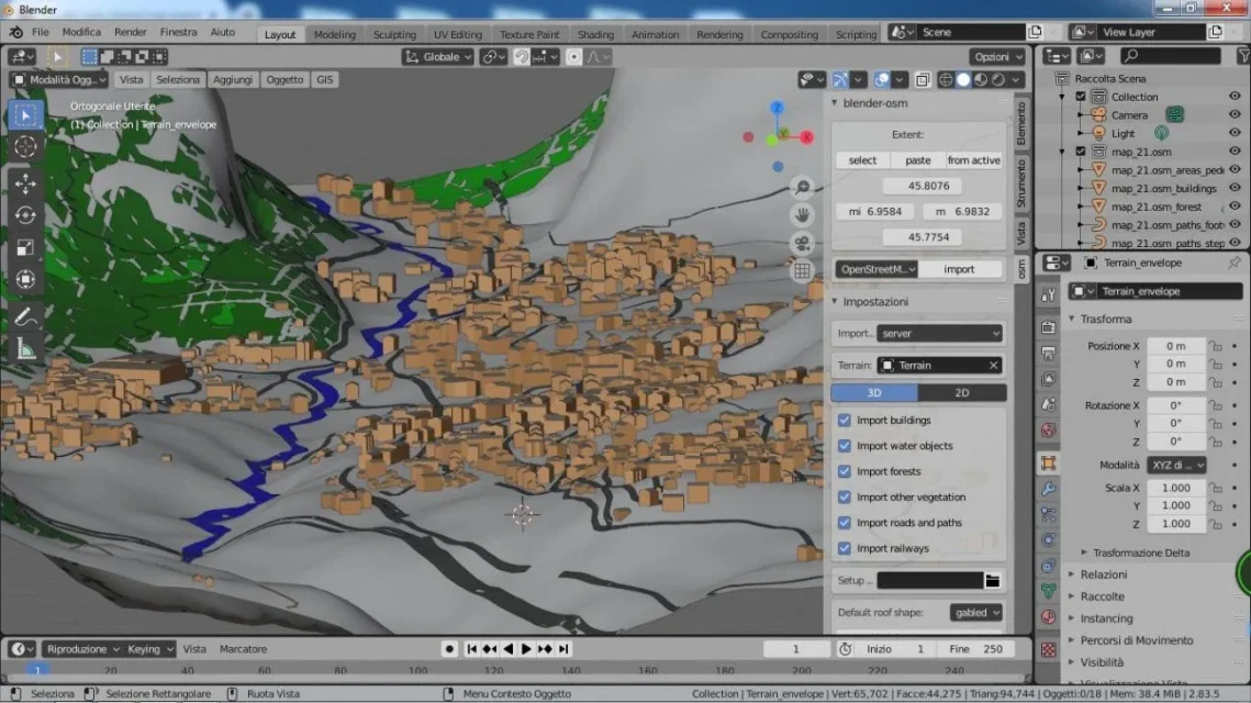
hello to all, I should create prospectuses from an aerophotogrammetry and until now I have always used Spartan and fast methods. Does anyone have ideas, tips, tricks to give me to help me in this job I hate? place of the images of example to make you understand: in the first image "aero" we find the aerophotogrammetry with the numbered buildings and the directions (fresh in yellow), I must create sections of all the buildings that pass through those directions both on the right side and on the left side (that is, as if we imagined before seeing from right to left and then from left to right).
Does anyone have any suggestions?
 

Attachments

  • aero.webp
    aero.webp
    173.2 KB · Views: 28
  • prospetti.webp
    prospetti.webp
    19.4 KB · Views: 30
If by spartan methods and little speed you mean the classic work of extrusion of polylines that identify buildings, then I fear that there are no other alternatives to that type of work.
more than anything else the most boring work, in my opinion, is to assign the heights (big way) to those solids. so you will have to consult google map, or google earth even to see if there is already a 3d representation of that area. then assign the heights to the extruded solids.

time I did a similar job to rebuild the altimetric trend on a town street on which one had to intervene with the construction of a rail line. They provided me with the video of the flyover via google earth. video that I processed with software for matchmoving, thus reconstructing the altimetric trend of the way, and building the 3d environment on which to insert the solids of the artifacts. Afterwards I gave them the video with the original video with the solids of the project, as a sorvolo that together with all the rest showed also the works in the project. .

If you're looking for it, it's all a lot easier. First of all, you should have an idea of the altimetric trend at the section line. the rest is easy to do.
I think the most ruthless part is the height of the palaces. Either way, it is convenient to recreate the 3d environment of that portion.
Is there already a 3d of that series of buildings, to be consulted on google earth?
 
Last edited:
If by spartan methods and little speed you mean the classic work of extrusion of polylines that identify buildings, then I fear that there are no other alternatives to that type of work.
more than anything else the most boring work, in my opinion, is to assign the heights (big way) to those solids. so you will have to consult google map, or google earth even to see if there is already a 3d representation of that area. then assign the heights to the extruded solids.

time I did a similar job to rebuild the altimetric trend on a town street on which one had to intervene with the construction of a rail line. They provided me with the video of the flyover via google earth. video that I processed with software for matchmoving, thus reconstructing the altimetric trend of the way, and building the 3d environment on which to insert the solids of the artifacts. Afterwards I gave them the video with the original video with the solids of the project, as a sorvolo that together with all the rest showed also the works in the project. .

If you're looking for it, it's all a lot easier. First of all, you should have an idea of the altimetric trend at the section line. the rest is easy to do.
I think the most ruthless part is the height of the palaces. Either way, it is convenient to recreate the 3d environment of that portion.
Is there already a 3d of that series of buildings, to be consulted on google earth?
the altimetric relief generally I do it with google earth where there is google 3d otherwise I come down with street view and I count the plans for each building (I will not have any remedy to this).
I would rather be interested in understanding what you mean by "poliline extrusion work", could you explain to me step by step what you mean?
My method is very spartan, I practically align the field of reference (the yellow line) horizontally on the floor (the line that would represent the altimetric trend of the area) and I make a xlinea vert of the buildings that intersect this sector, then I draw the rectangle with the heights I have previously detected from google.
 
I think it's more convenient to polish with autocad the photogrammetric, placing the map itself as a background, giving it some transparency and recalculating through polylinees those that are the edges of the buildings affected by the section line, including also some edge of the streets. after which to extrude each polyline that identifies each building according to the height that has been estimated (adjusted by observation from street view or by inspection on the spot).

a 2d polyline extruded at a certain height will give rise to a solid, which in our case will represent the building.

Afterwards with autocad and with the command section piazzi the section making it correspond with the yellow one. at that point you have both sections, seen both on one side and on the other. Once the solids of the buildings were created, it will think about autocad to give you the section. You just have to decide where to fix it. As for the altitude of the country plan, you should see if in the photogrammetric you have at your disposal there are quota references. Otherwise you can calculate it with discreet approximation from more visuals of the affected area and working on match moving. matchmoving programs also recreate the 3d environment by taking as points references. in your case the reference points to be taken for the matchmoving are those that identify the road plan.

to avoid matchmoving it would be better to check if in the photogrammetric there are quota references. In that case, it's all easier.
 
Last edited:
Thank you for the very detailed explanation, but unfortunately I tried all morning but I couldn't do what you explained to me, would you be able to make me a short demonstration video? I know I'm asking a lot, but your method seems really revolutionary for my job and I'd like to see if it really is.
 
in this way.
the mouse wheel abandoned me and did not allow me to make the pan.
attach the picture in good resolution of the photo you want to polish. carry it in scale and then polish the lines that interest you with the polylinea command, including the eyelashes of the streets. extrude giving a height to solids. I've been watching, even for the ladder. to speed up the video I polished one palace and copied it in series.
then with the section command and the sub-command "draw section" draws the section making it correspond with the yellow line.

to change view to the section simply click on an arrow-shaped icon that is displayed when selecting the section plan. you can choose from which side the section should look. Finally with the command create autocad section draws the selected solids.
autocad applies a grey retino to sectioned surfaces.

for the country plan you should create a flat surface adapting it to what is the real trend of the ground.
 
Your method really seems revolutionary for my work and I would like to understand if it really is.
in reality are the programs cad the real "revolutionary".
passing from the old tecnigraph to the cad I also had to review some methods of approach to various problems.
Just like you, to make prospectuses and sections of a building, first I drew the country plan then with the plant I pulled lines, as I did with the tecnigraph. I still do, in case the prospect is simple. but if it's complicated then I prefer to create solids and with the section command will be the cad to do the most ruddy job.

in your case you will have to spend some time polishing, but it is a simple job that does not commit too much.
 
Thank you very much for everything, I will treasure your suggestions and try to put them in place. I tried a little tonight and I still can't really do it, but it's just a matter of practice.
 
I believe that as a method you avoid pulling up every line that intersects the section line when you do the prospect.
Sometimes, depending on the number of solids created, you have difficulty displaying the dart icon that allows the change of view in the section plan (as happened to me in the video). in such case it is convenient to isolate the section plan and then select it again. the created section then finishes "hand" according to your viewing preferences.

the rotation of the cursor I carried out with the snap command and under control "r" (rotate) by typing from the keyboard.
sub-command "r" that does not appear in the list of subcommands of the snap command, but that is still present. to bring it back as before the r command sets everything to 0
(0,0 sending, 0)
 
but that is not photogrammetry, the 3d relief should be done by hand, the photogrammetry is done with drones,
for what you have to do there are faster methods with 3d tools like blender and sketchup
see images below some of my evidence, where I used open street map
 

Attachments

  • ostiense.webp
    ostiense.webp
    238.1 KB · Views: 10
  • courmayeur.webp
    courmayeur.webp
    144.5 KB · Views: 12
  • cerenovamare.webp
    cerenovamare.webp
    128.3 KB · Views: 14
but that is not photogrammetry, the 3d relief should be done by hand, the photogrammetry is done with drones,
for what you have to do there are faster methods with 3d tools like blender and sketchup
see images below some of my evidence, where I used open street map
I have no idea what blenders and sketchups are, anyway I would need to present them in 2d it is possible to do it with these methods?
 
the map placed by brandotw is an aero-photogrammetric.
are maps in 2d obtained from aerial photos. exist for many years. are also provided in dwg format, as well as on paper.
are vectorizations performed using aerial photos.

photogrammetry as it is understood today comes only recently. today thanks to the possibility of sending drones, and thanks to the software it is possible to obtain more information from the photos that are not only those obtained from a view from the top of a single photo. today we use photos taken in sequence. the drones record the video and from the video the software extract the frames that will serve to reconstruct the altimetric trend of the ground.
I was talking about matchmoving first. Actually, modern photogrammetry software performs work similar to that of the most traditional matchmoving software.
create a 3d environment from a sequence of 2d images.
 
I have no idea what blenders and sketchups are, anyway I would need to present them in 2d it is possible to do it with these methods?
it is possible to do the opposite, that is from a 2d sequence to get to create a 3d environment.
where only a few highlights or a cloud of points are meant by 3d environment.
modern photogrammetry programs try to get as much information as possible from a sequence of photos to return a cloud of points
But they are enormously demanding in terms of quality of the images to be processed and in order to achieve an acceptable result they take a long time to return our cloud of points.

traditional matchmoving programs do not return any cloud. only of the highlights that are operating to identify in the environment 3d.

For example, from this survolo video made with google earth I reconstructed the mesh 3d that identifies the area of intervention, along with its altimetric trend. I used syntheyes for the matchmoving. because I didn't need to have a whole cloud of points, but only those points relative to the asphalt plane that would allow me to draw the plano altimetric of the way.
a mesh 3d on which to draw design solids, mesh 3d obtained from a sequence of 2d frames

that in blue is the mesh 3d inserted in video 2d.
It is not thinkable to do such a thing with a photogrammetry program. a software for the machmoving, or tracking (in this case manual) of the points we are interested in. in the specific case of the points visible in the frames and traceable. points that can be oil stains on asphalt, side edges etc. Finally, these points are connected and mesh is created.
you could also do for the walls of the buildings to reconstruct the approximate height, but it is necessary of the software that allows the tracking of the points
 

Attachments

  • pianta tracciato.webp
    pianta tracciato.webp
    9.3 KB · Views: 8
  • prospetto tracciato.webp
    prospetto tracciato.webp
    14.7 KB · Views: 7
the map placed by brandotw is an aero-photogrammetric.
are maps in 2d obtained from aerial photos. exist for many years. are also provided in dwg format, as well as on paper.
are vectorizations performed using aerial photos.

photogrammetry as it is understood today comes only recently. today thanks to the possibility of sending drones, and thanks to the software it is possible to obtain more information from the photos that are not only those obtained from a view from the top of a single photo. today we use photos taken in sequence. the drones record the video and from the video the software extract the frames that will serve to reconstruct the altimetric trend of the ground.
I was talking about matchmoving first. Actually, modern photogrammetry software performs work similar to that of the most traditional matchmoving software.
create a 3d environment from a sequence of 2d images.
Exactly!
it is possible to do the opposite, that is from a 2d sequence to get to create a 3d environment.
where only a few highlights or a cloud of points are meant by 3d environment.
modern photogrammetry programs try to get as much information as possible from a sequence of photos to return a cloud of points
But they are enormously demanding in terms of quality of the images to be processed and in order to achieve an acceptable result they take a long time to return our cloud of points.

traditional matchmoving programs do not return any cloud. only of the highlights that are operating to identify in the environment 3d.

For example, from this survolo video made with google earth I reconstructed the mesh 3d that identifies the area of intervention, along with its altimetric trend. I used syntheyes for the matchmoving. because I didn't need to have a whole cloud of points, but only those points relative to the asphalt plane that would allow me to draw the plano altimetric of the way.
a mesh 3d on which to draw design solids, mesh 3d obtained from a sequence of 2d frames

that in blue is the mesh 3d inserted in video 2d.
It is not thinkable to do such a thing with a photogrammetry program. a software for the machmoving, or tracking (in this case manual) of the points we are interested in. in the specific case of the points visible in the frames and traceable. points that can be oil stains on asphalt, side edges etc. Finally, these points are connected and mesh is created.
you could also do for the walls of the buildings to reconstruct the approximate height, but it is necessary of the software that allows the tracking of the points
the job is very charming and very far from my skills but I don't think it can serve me for my goal (or I'm stupid and I can't see how to use these techniques to do my job).
 
I don't think I could use my goal.
You wouldn't need it because you already have the plan to work on.
but in case there was no possibility of having a planimetry you could use a flyer of the affected area, i.e. a sequence of images like the frames of a video (or photos taken at certain intervals of space).
is what modern photogrammetry programs do or matchmoving programs do.
 
Of course you do your views and sections and carry them in dwg e.g.
then it is more convenient to check through google earth if the 3d of the buildings are inserted in that area.
in the video of the city flyer I posted before the buildings are in 3d.
 

Forum statistics

Threads
44,997
Messages
339,767
Members
4
Latest member
ibt

Members online

No members online now.
Back
Top