• This forum is the machine-generated translation of www.cad3d.it/forum1 - the Italian design community. Several terms are not translated correctly.

fatigue analysis with use of finished elements

  • Thread starter Thread starter Matticip
  • Start date Start date

Matticip

Guest
Hello everyone,

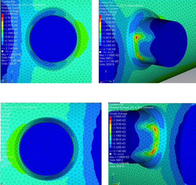
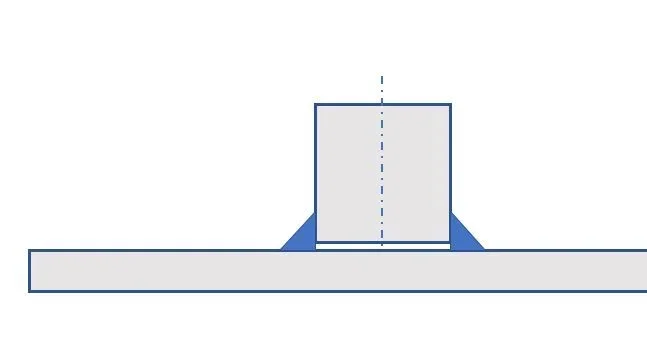
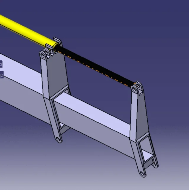
I am trying to set a fatigue analysis, on the pins welded on the cylinder shown in the figure, using the fem analysis with the help of the software Altair, I wanted to know if there is a "module" to solve this type of analysis or if once obtained the results from the static analysis I have to proceed theoretically with the various formulas available in literature.
I hope I have been clear enough, I thank in advance anyone who can give me help or guidance on this.
ps:Risultati prova.webpon this specific case another doubt that arises to me is if the fatigue test of the pins is linked to that of the welds, i.e. I wonder if it is right to affirm "check the fatigue welds the number of life cycles of the welds and the pins are coincident as the welds coming to break are broken in correspondence of the base material and not of the one from intake"
pps: any help on how to set a generic fatigue analysis with a fem software is well accepted
 
Hello matticip,

at a first glance at the tension path, I will be wrong, but I think you shaped him badly.
send us a mesh image to the interface between welded bushings and cylinder?

passing specifically, hyperworks has the form for oligocyclic fatigue and a high number of cycles. You could also track a haigh diagram and see what is the safety factor you are working with (it is an approximation but gives you starting numbers).

Other programs that are even more specific for the evaluation of fatigue life are femfats and ncodes (used in automotive and not only) but also many others.

Unfortunately I cannot give you a more detailed answer than your question (it is a physical limit).

Give us more information and we'll tell you more.
hi hope and thanks for the answer, I apologize for the lack of data I will try to be complete.
In the annex I put the detail of the mesh required by you (in making the catches I noticed a noticeable difference between the two pins that I believe is linked to the cad model and not to the mesh).

I try to explain the situation you want to simulate with this model because the error could be precisely in the setting being these my first analyses:

we want to evaluate the fatigue life of the pins welded on a cylinder of a linear actuator of the length of 2000 mm (of which only 500 are used in the finite element model) working at a pnominal of 340 bar, the simulated phase is that of return (p in the front room, of which I attach a skeatic sketch);
in setting the model I have blocked the nodes of the area to in all directions and in all rotation, while the knots in the area b are blocked only in rotations, the pressure of 340 bar is applied on the crown with outwards along the axial direction (as in the hand scheme) and also in radial direction outwards on the entire inner surface of the cylinder.

by entering into specific fatigue analysis:
the actuator works 3 times in 1 day for a total of 365 g/year and must move a payload of 14kn during its cycles

I hope I have not left out again important information
 

Attachments

  • BCs.webp
    BCs.webp
    57.5 KB · Views: 23
  • Dettaglio mesh perni.webp
    Dettaglio mesh perni.webp
    328.9 KB · Views: 23
  • Memo20180804_102257.webp
    Memo20180804_102257.webp
    21.4 KB · Views: 20
  • Risultati.webp
    Risultati.webp
    288.5 KB · Views: 20
Hello matticip,

I would not enter for the moment in the discourse fatigue because on welds is quite complex and that is always riding between the theorist and the experimental. Are you solving this exercise for a university exam?

Can you show us the mesh section on the welded bushing? on hypermesh you can use f5>mask elements. those bushings are usually welded in mask and should not have no matching knots with the cylinder (enclosed image), instead I suspect you have meshato the block.

I'm progressing step by step.

You told me how you bound the component but I can't tell you if it's right or wrong because the fem is just a modeling of reality and if you don't tell me what it is, I don't know how to tell you if it was approximated well.

I am sure that, in any case, there is something wrong at least theoretically in the constraints you used as in solid elements the knots do not have degrees of freedom of rotation.

I also add that, there are standards to follow to check static welding and fatigue Eurocode 3 etc. users of the most experienced forum will definitely intervene.

here is an interesting reflection made by mechanicsmg: https://www.cad3d.it/forum1/threads/verifica-saldature-eurocodice-3-hot-spot-sress.52443/If you are looking for the forum find a lot on this topic.
 

Attachments

  • boccola saldata.webp
    boccola saldata.webp
    2.2 KB · Views: 16
Hello hope,

I will try to clarify the context so I hope it will be all clear : the problem is at the didactic level for a university examination (construction of machines), the actuator is the smallest of those dealing with the handling of the wires of the telescopic arm of a truck crane (the crane is the machine we are planning and this of the actuator is one of the problems that I and my group are currently facing); the conditions I have previously listed were obtained in the previous stages of schematization/design of the machine.

returning to the problem of modeling:the pin actually penetrates into the cylinder not leaving that space you see in the figure you have attached (I attach section of the cad of my model).

It was initially left a "space" between the pin and the cylinder but the professor said that it was not properly correct because the welding goes however to create continuity between the two basic materials (or better this is what my group understood, we may have misunderstood the words of the professor); is that space prescribed by law or is it common practice to leave it?(I wonder if it is an obligation or a shortness by the analyst to leave it to obtain a more correct analysis)

regarding fatigue:
- for this specific case we will be able to comply with the regulations you have indicated to me and to guide the iiw(international institute of welding); Does this imply that the fatigue on the pins is not necessary to study it as it is enough that on the welding?(i.e. if there is a fatigue yield happens for the welding before even on the pin? )
- you have some reference links for the Altair section dedicated to fatigue analysis for a generic component (not necessarily with soldering) because I searched on the internet but I did not find any sort of guides, so it would be very useful for studying the next components of the project

thank you again for the availability
 

Attachments

  • dettaglio perno.webp
    dettaglio perno.webp
    12.4 KB · Views: 14
I continue not to see a clear representation of load conditions and constraint on this component. as has already said hope welding fatigue analysis is a type of study still a little semi-empiric. wanting from software even a fatigued fem analysis of a soldering seems a little too much. If the pin or welding is broken first, of course the answer is: depends.
But isn't there any way to schematize this component and try to pull out two hand numbers?
"I continue not to see a clear representation of load conditions and bond on this component" I did not understand if I am not clear in explaining the operational situation of the component or if you refer to how the model is set, I carry what previously said to try to explain both:
"We want to evaluate the fatigue life of the pins welded on a cylinder of a linear actuator of the length of 2000 mm (of which only 500 are used in the finite element model) working at a pnominal of 340 bar, the simulated phase is that of return (p in the front chamber, of which I attach a skeatic sketch);
in setting the model I have blocked the nodes of the area to in all directions and in all rotation, while the knots in the area b are blocked only in rotations, the pressure of 340 bar is applied on the crown with outwards along the axial direction (as in the hand scheme) and also in radial direction outwards on the entire inner surface of the cylinder. "

I'm not asking the software to do a fatigue analysis on welds (for those we already knew we had to refer to the rules in force) I'm asking if there is in the software a section for fatigue analysis on a component genre and free of welds, I have repeatedly underlined by the first message that my problem was on generic and unwelded components.

how do you suggest to hand-treat a rough component(and not treatable with beam theory) as the pin in question?
 
in post 3 you said that you completely blocked the knots of a certain area a and blocked the rotations of a certain area b. It is not clear why. it is not clear what real constraints are: that pin, in the opposite end of the cylinder is hinged? soldered to something else? is important information, but it is not clear. hope asked you.

Don't take it personally.

most software have modules for fatigue analysis with the methods already implemented. I can't tell you, I had done something with
Ansys.

There are also models for the books on literature. in any case the difference if I do not remember the difference from the slender beam lies in the calculation of the arrow that depends both from moment and from cut, but the cardinal equations of the static and therefore the course of the internal actions and the efforts, it is however worth.
 
ok now I understand what you meant with lack of data; the pins are hinged in a flange (allego screen del cad).

As for the theory we will review well in literature but I do not remember, neither I nor the others, a part dedicated to the travails, the same professor has prompted us to carry out an analysis to the finite elements for such elements (we have for scruple applied the same procedure of the slender beams but evidently wrong results, could be our lack of course)

I try to provide you with the data you require with the attached images, now being a model put up quickly to give you this answer will present several errors and lacks of fundamental elements (such as shoes for the relative motion) therefore do not make us case, I put only in evidence that the locks for the pins of the actuator will obviously be to the eye and then will hug the pin and not teamed as here represented, hope that it was missing

at the other end the actuator is obviously left free, the only constraints are the hinges depicted here
 

Attachments

  • Cattura.webp
    Cattura.webp
    34.1 KB · Views: 18
  • Cattura2.webp
    Cattura2.webp
    53.3 KB · Views: 17
  • Cattura3.webp
    Cattura3.webp
    33.9 KB · Views: 16
It is not trivial at all to shape that kind of bond. I’m not sure but that trend of efforts you posted in the first post might also be right. We wait for someone else's opinion. As soon as I have time I make an attempt.
 
It is not trivial at all to shape that kind of bond. I’m not sure but that trend of efforts you posted in the first post might also be right. We wait for someone else's opinion. As soon as I have time I make an attempt.
thank you for the availability I will wait for any updates if you have a way and time to make an attempt, thanks again for the intervention
 
I try to give you more information but it is difficult to respond concisely.

if you are studying welding and models all as if the bushing was in complete penetration (when it is not), then it makes no sense to study welding.

in many cases, to increase the resistant section, the bushings are cyanphrined (smused) but hardly (as opposed to the plates) are in complete penetration. in the case of welding in complete penetration the welding is not modeled but takes into account the different intake material and the thermally altered zone reducing the local safety coefficients obtained.

If you want to study the overall behavior of your piece I agree with your prof, you do not need to model the cylinder-box interface and at least welds. but if welds are the object of the study, then you cannot consider everything as if it was a unique body.
light is not standard or standard, and may not be there, but in any case you cannot have the mesh knots matching the interface.

Now that I see pictures about the mounting I understand more. the image unfortunately is cut and the actuator is not complete but there is something that does not return to me. Are you sure there will be a reaction on the bushings? hydraulic cylinders theoretically work well with axial loads.

then, if I'm wrong and the reaction is really (but I don't think), in hypermesh you can shape contact with the contact manager. tools> self-contact and activation card nlparam

for fatigue in hypermesh/optistruct you can watch stress-life (s-n) approach and strain-life (e-n) approach.

under tools> fatigue process> create new (if you have installation in English) you can create the process.

Let me know if you need help with hypermesh.
 
at the other end the actuator is obviously left free, the only constraints are the hinges depicted here
I'm sorry, I've read back as well as you wrote. I would model that area with a contact, so also consider the girdle of the eye. Alternatively to extract the loads to be applied theoretically to the welding you can use the free body diagram (I don't know if it works with the student license). you could also do a comparative analysis of the results you get from the fem and those that revenues from the standards.
 
I try to give you more information but it is difficult to respond concisely.

if you are studying welding and models all as if the bushing was in complete penetration (when it is not), then it makes no sense to study welding.

in many cases, to increase the resistant section, the bushings are cyanphrined (smused) but hardly (as opposed to the plates) are in complete penetration. in the case of welding in complete penetration the welding is not modeled but takes into account the different intake material and the thermally altered zone reducing the local safety coefficients obtained.

If you want to study the overall behavior of your piece I agree with your prof, you do not need to model the cylinder-box interface and at least welds. but if welds are the object of the study, then you cannot consider everything as if it was a unique body.
light is not standard or standard, and may not be there, but in any case you cannot have the mesh knots matching the interface.

Now that I see pictures about the mounting I understand more. the image unfortunately is cut and the actuator is not complete but there is something that does not return to me. Are you sure there will be a reaction on the bushings? hydraulic cylinders theoretically work well with axial loads.

then, if I'm wrong and the reaction is really (but I don't think), in hypermesh you can shape contact with the contact manager. tools> self-contact and activation card nlparam

for fatigue in hypermesh/optistruct you can watch stress-life (s-n) approach and strain-life (e-n) approach.

under tools> fatigue process> create new (if you have installation in English) you can create the process.

Let me know if you need help with hypermesh.
Welding is the design of the study, the bushing has been shaped in complete penetration because it seemed like a feasible approach theoretically and we had no other real recons on which to base ourselves, now we will try to reshape it more closely to reality according to what you have swallowed us.

I also thank you for the various tips on using hypermesh, unfortunately I use it too little to say that it is all clear to me (cause of my lack in knowledge of the software obviously) as soon as I have the pc by hand I try to follow your directions and I will rewrite here below in case of need.

thank you very much for patience and clarity in the answers, I will keep you updated on the final result
 

Forum statistics

Threads
44,997
Messages
339,767
Members
4
Latest member
ibt

Members online

No members online now.
Back
Top