Karim_The_Dream
Guest
Hello everyone, I apologize first of all for the time, I introduce myself to myself as karim and I am a student of industrial engineering.
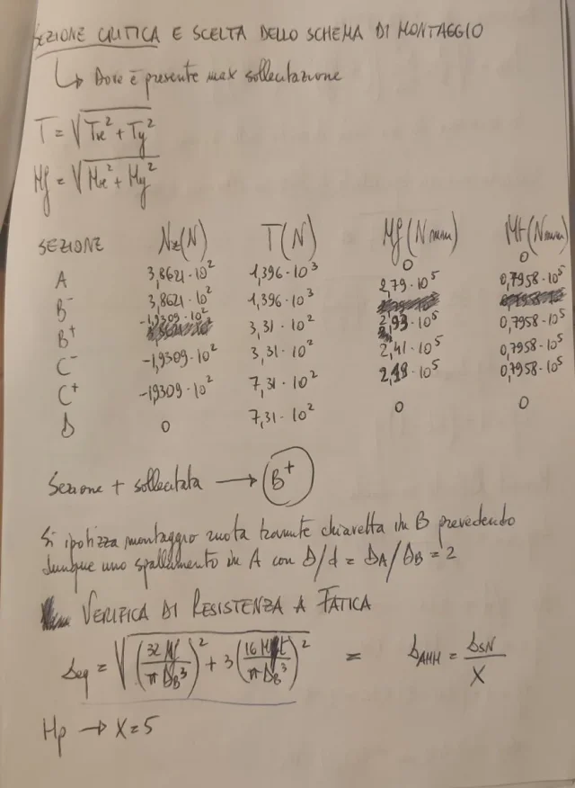
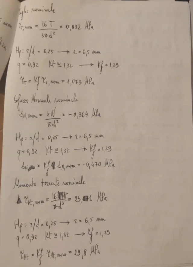
I write because I have doubts in the resolution of an exercise of examination of fundamentals of construction of mechanics that relates precisely to the fatigue dimensioning of a tree. I have already seen some older discussion on the question of fatigue-sizing but I have found nothing that could help me solve my doubts so I decided to create this discussion. I attach the exercise and my conduct, I have arrived until the fatigue test of the most stressed section, the b, where the pinion is located.
what I should do to finish the exercise is to hypothesize a mounting scheme for the other wheel in c, to check fatigue also and then to make a sketch of the tree with the diameters obtained and the other suppositories and it is here that the doubts begin, or better, already from when I set a mounting scheme for the first wheel in b (more stressed section). a lesson simply the question of assembly is resolved by saying "it is hypothesized assembly wheel through key and shouldering in previous/successive section" but to me it seems a little too reductive as a solution also because I can not understand how after you can get to make a sketch of the entire tree (with its diameters) having dimensioned only the most stressed section, that is that of the b wheel (pignone). I would like to have the clearest ideas regarding the procedure to follow for the fatigue dimensionalization and then arrive at the final design with all the diameters in each section.
for the calculation of the fatigue limit and the kt I have served some formulas and graphs present on the juvinall.
I hope I've made myself understand, thank anyone who can help me.