You are using an out of date browser. It may not display this or other websites correctly.
You should upgrade or use an alternative browser.
You should upgrade or use an alternative browser.

Mike1967
Guest
check the options in the parameters. I'm in charge.swx 2010 sp.4
I am making tables on parts shaped by my client (first work "real" with swx).
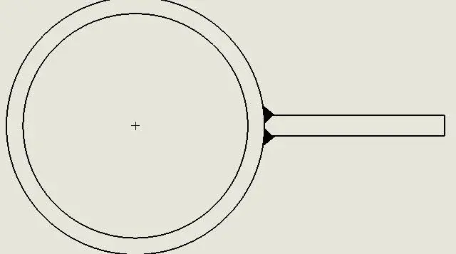
I can't complete a welding cord using the "Final Treatment" function (see attachment), do I have to do it by hand?
swx 2010 sp 4
Attachments

cacciatorino
Guest
You seem to have the same problem I have. I want the area where the cylinder goes in tangence with the plate to be filled.check the options in the parameters. I'm in charge.
swx 2010 sp 4
lelepanz
Guest
I have often created blocks to cover these shortcomings.
If you mean that the inside would be "fielded".
If you mean that the inside would be "fielded".
Mike1967
Guest
But why do you want to fill that space?You seem to have the same problem I have. I want the area where the cylinder goes in tangence with the plate to be filled.
so says the norm?
However the problem is bypassable.
note that my plate is detached from the tube, to make the idea better.
Attachments

lelepanz
Guest
when I was working in the "recipients" in vcon autocad pressure we stole. or we were shaped, so as to "hide" the space.
Bad to say and do, good to have a good time.
Bad to say and do, good to have a good time.
marcof
Guest
a question of pure curiosity: Why don't the cord do it in the model, where the filling would be correct?swx 2010 sp.4
I am making tables on parts shaped by my client (first work "real" with swx).
I can't complete a welding cord using the "Final Treatment" function (see attachment), do I have to do it by hand?
lelepanz
Guest
sampom
Guest
I don't remember anymore.a question of pure curiosity: Why don't the cord do it in the model, where the filling would be correct?
with 2009 could you already put the cord between a round face and a plain with the void in the middle? I think it's only since 2010. .
only that then on the table in the section you have to change the sample to be held solid (black), but this would be quick to do.
is that if you have so many we know how "heavy" welds in the model (in 2011 they lightened them; is no longer a "solid" but entirely a cosmetic. . However the external aesthetic is painful, alternating bands white and black, seems the cuxor the bee maia:smile
") .
.the final treatment "fills" the area between the 2 selected lines (until the apparent intersection). there in the inside you have a third line, clear that it remains excluded from the selection.swx 2010 sp.4
...I can't complete a welding cord using the "final treatment" function (see attachment), do I have to do it by hand?
you can do or as marcof says, in the model, and then blacken the sampling.
or at the table with treatment:
- first preparing the edges cianphrine them (smusses) and select the line of the bevel and the circumference of the tube.. that if you have big thicknesses and you want penetration even "from the real" you should do so.
- if you select the circumference and the tangent inner line fills only that space but externally the cord remains very small (and inverosimile).
- make the treatment in 2 times.
first with inner line and circle (as above), ok. then with outer line and circle. the 2 fields overlap and see only one as you wish.
Try how you like it and you're more comfortable.
greetings
Marco:smile:
p.s. and the sections reverse the angle of 90° between tube and plate.:biggrin:
sampom
Guest
Is there no final treatment or the caterpillar in the tables?swx 2010 sp.4
I think it's a pass on, right?
:tongue::
greetings
Marco:smile:
cacciatorino
Guest
They are models that gave me the client, I just have to make the table.a question of pure curiosity: Why don't the cord do it in the model, where the filling would be correct?
cacciatorino
Guest
no in fact, I don't know if in recent versions they put it, you know that I am always 12 releases back.Is there no final treatment or the caterpillar in the tables?
I think it's a pass on, right?
:tongue::
greetings
Marco:smile:
Welding cords can be made in 3d, with the special "weldment" environment.
cacciatorino
Guest
This doesn't work well, in the sense that when I go to do the sampling of the inner part comes out a gushing medium, however I am sure I have not yet understood how the command works. But in the end, it's not that important. I just thought I didn't understand how to use the command.first with inner line and circle (as above), ok. then with outer line and circle. the 2 fields overlap and see only one as you wish.
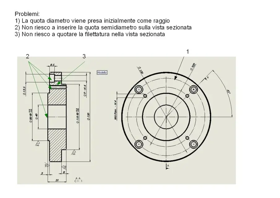
Of course, but to put a diameter stake on a circle in the plant, he first puts the radius, then I have to say that no, look that I want the diameter, then finally I have to tell him that I want both the terminators because on the diameter quota it takes two, I just told you to put the diameter, not the radius, do not pretend you didn't understand and as usual do the things half.... :biggrin:

sampom
Guest
1) I think I understand what you say: a pipe industry is blacked out or in any case a "strange" area1) this does not work well, in the sense that when I go to do the sampling of the inner part comes out a medium gushing, however I am sure I have not yet understood how the command works. But in the end, it's not that important. I just thought I didn't understand how to use the command.
2) Of course, but to put a diameter stake on a circle in the plant, he first puts the radius, then I have to say that no, look that I want the diameter, then finally I have to tell him that I want both terminators because on the diameter quota it takes two, I just told you to put the diameter, not the radius, do not pretend to have understood and as usual do the things half.... :biggrin:
you have to do the third clik "in the void" by moving the mouse to the direction where you want the black triangle to appear. prove that taking your hand is automatic.
2) also here I understand. .
but no, it can depend on how the particular round is shaped. if the circle is "incomplete", interrupted, cut etc. as first solution he gives you the radius. depends also on how you move the quota, for "inside"/finished circles moving a little mouse see that it presents you different solutions and that of the horizontal or vertical diameter is always immediate to get. .
in these cases it is precisely question "of handle" (..saperlo "muovere"):biggrin:
greetings
Marco:smile:
sampom
Guest
Well, this is normal and also in swx. both in part (multibody:biggrinWelding cords can be made in 3d, with the special "weldment" environment.
and together.. but you've seen it.greetings
Marco:smile:
Last edited:
sampom
Guest
..and if you refer to that section that you attached, in that floor passes the hole that also crosses the wall of the pipe.But to put a diameter stake on a circle in the plant, he first puts the radius, then I have to say that no, look that I want the diameter, then finally I have to tell him that I want both the terminators because on the diameter quota it takes two, I just told you to put the diameter, not the radius, do not pretend you did not understand and as usual do the things halfway... .
as I told you before that is no longer a continuous circle and the automatic quota indicates the radius by default because you are measuring an arc.
if you imported the quotas from the model you would have the diameter (if in the sketch you assigned the diameter).
greetings
Marco:smile:
re_solidworks
Guest
the way + fast to make that quota is:..and if you refer to that section that you attached, in that floor passes the hole that also crosses the wall of the pipe.
as I told you before that is no longer a continuous circle and the automatic quota indicates the radius by default because you are measuring an arc.
if you imported the quotas from the model you would have the diameter (if in the sketch you assigned the diameter).
greetings
Marco:smile:
quotate the radius and place the radial quota in horizontal or vertical, click on the membership line tab and turn the quota into "line".
you can get the same result also with the radial quotas placed with different angles, but in that case you will have to click the linear quota and orient it by razoring the appropriate grip above the text.
cacciatorino
Guest
Excuse me, I put an image so clearly where I met these (superable) problems.
re_sol:
I did not understand what you mean by turning the quota as linear, when I give the command the quota disappears (they only hold the handles, and as soon as I touch the quota evaporates).
re_sol:
I did not understand what you mean by turning the quota as linear, when I give the command the quota disappears (they only hold the handles, and as soon as I touch the quota evaporates).
Attachments
cacciatorino
Guest
Okay, all clear, it's just that the length of the welding was fixed at 5 mm and it didn't come to fill all the space, I lost myself in the classic water bicker. thanks anyway for the indication!1) I think I understand what you say: a pipe industry is blacked out or in any case a "strange" area
you have to do the third clik "in the void" by moving the mouse to the direction where you want the black triangle to appear. prove that taking your hand is automatic.
