• This forum is the machine-generated translation of www.cad3d.it/forum1 - the Italian design community. Several terms are not translated correctly.

helical scale

  • Thread starter Thread starter Ompu
  • Start date Start date

Ompu

Guest
I'll give you my problem.
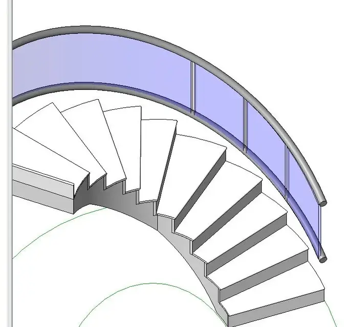
I have to create a helical scale in revit, of course through the boundary scale command. I saw the impossibility of creating forms of ellipses with such command, and therefore I created it through numerous arches at 3 points.
But my problem is in the railing. I would like a continuous tubular handrail that follows the profile of the scale (a 3d helical spline, we say), but I get this type of discontinuity, even changing the connection type of the joint.
catturaqx.png

cattura2y.png
I then thought of creating it with a local model, but I can't find the way to create a route extrusion with a 3d path (a 3d propeller for precision).
I also have the problem that I would like to insert glass balustrades that partially follow the curvature of the section in which it is positioned.
could you explain to me the correct way to create this railing (or how to shape it in solid? )
thank you very much for the availability
 
Did I say one thing about the genre?:rolleys:
 

Attachments

  • 001.webp
    001.webp
    33.5 KB · Views: 68
  • 002.webp
    002.webp
    40.7 KB · Views: 41
was exactly what I meant, could you please explain to me how you managed to achieve it?
Thank you very much for the future answer and for what you gave me, at least now I can hope that this is not an impossible operation
 
even if little bim, since the elliptical stairs with the drawings and with the railing there are problems, I created the railing with the modeling in place.
I left the original ringhera as the basis for the design. then I created the first current with union on path. I copied the current to get the lower one. then merge on path to realize the glass, which subsequently goes 'empty' with a vacuum from simple extrusion.
I did it fast, helped with the reference plans.
bye:
 
but how did you create the path?
I'll explain. I do not have a 3d propeller to be selected as a path, and I can not even select as a path that of the railing as it presents discontinuities, therefore it does not create a perfect "elica". maybe it was the way to draw the scale that was wrong, could you kindly explain to me about the method you used? Thanks again
 
as it says roberto, the path of the handrail must be composed of only one segment, otherwise it interrupts the continuity of the same.

using the ellipse design, the side of the handrail, you have to draw it as the only segment.

p.s. if in drawing the ladder, in drawing the contour you can make a single ramp up to 360° (using the various ways to track the lines offered by the field "drawing"), all manages simpler

for shaped panels, you have to differentiate the size: a 100 cm base glass panel hardly follows the "street" curve of the ellipse, so the panel must be shorter.


p.s.s. have you evaluated the cost (real) of glass panels, curved and shaped?
 

Attachments

  • ScalaE.webp
    ScalaE.webp
    96 KB · Views: 67
Last edited:
ca gfrank, in reality there is a way to get scales with angles greater than 360° (in drawing mode) even if it sometimes does not draw them correctly.
Bye. good work:finger:
 
ca gfrank, in reality there is a way to get scales with angles greater than 360° (in drawing mode) even if it sometimes does not draw them correctly.
Bye. good work:finger:
Hi roberto,
... but, put the carrot near the mouth, and then remove it...
How?
 
hi gfrank, when drawing the curvilinear scale, draw the first part with the > circular ramp command (it will not make you exceed the angle of 360), then reclick the > circular ramp command, active snap center mode, click in the center and redesign the part that is missing from the last track, close.
as I told you is not the max especially regarding the railing.
bye:
 
I got a good result following your frcprogetti advice, but I can't create the glass balustrade, with path union the reference planes position me tilted, and the profiles as well. How can I make them perpendicular to the ground floor in such a way that the balustrade is created?
 
published my question more generally. is it possible to change work plans in a path union (or even in a route extrusion) by selecting a 3d line?
 
you must first define which are the reference plans, possibly creating new ones, even inclined and creating extrusion with the use of these plans.

There is a default family to create the "mounters" that contains the tilt parameter according to the ramp.

p.s. given the peculiarity of the staircase (ellisse) and of the panel (travel curved "with variable radius") perhaps it is easier to make the panel "only" with an extrusion on path (in pole) that follows the profile of the handrail and then with "empty" remove the panel parts in the various points of the scale, or many single extrusions as are the panels: made the first two ramps, for the next floors just copy them. . .
 
Good day I wanted to ask you how I could solve the problem with my ladder.
thanks in advance igo the jpg
 

Attachments

  • Immagine.webp
    Immagine.webp
    65.2 KB · Views: 12

Forum statistics

Threads
44,997
Messages
339,767
Members
4
Latest member
ibt

Members online

No members online now.
Back
Top