• This forum is the machine-generated translation of www.cad3d.it/forum1 - the Italian design community. Several terms are not translated correctly.

help on loft

reggio

Guest
Hi, I have difficulty getting what I had set myself up:

- create driving path
- create various sections along the path
- join everything with a loft and close it on itself

...I lock myself before... :frown:
Do you have the strength to look at him and give me a bucket of straight?

allego image and renamed file (only remove the ".zip")
 

Attachments

Hi, I have difficulty getting what I had set myself up:

- create driving path
- create various sections along the path
- join everything with a loft and close it on itself

...I lock myself before... :frown:
Do you have the strength to look at him and give me a bucket of straight?

allego image and renamed file (only remove the ".zip")
attachment not working. . :finger:
 
Hi, I have difficulty getting what I had set myself up:

- create driving path
- create various sections along the path
- join everything with a loft and close it on itself

...I lock myself before... :frown:
Do you have the strength to look at him and give me a bucket of straight?
Assuming that I don't understand how that tape can change shape while scrolling and above all as it flows on a cylindrical roller (but these will be business and yours :tongue:) I looked at the file and:
1) for how you made the path the section would intersect the two lower ridges, so you have to move the path above the small rollers
2) you have to use that sketch not as a path but as a line of half-carry
3) i have if you need a precise path you have to do a section for each direction change, so they are two for each reel
4) I would not make a single loft but I would break it in two or three sections, and however one that contains the concave profile in the center and two straights at the extremes
5) you must set the normal end and start path constraints to porphylo
6) maybe do it with two or three loft surfaces to join and then thicken could be easier than turning rectangles and that concave profile to get solid
7) maybe you also need two external routes
 
premise that I don't understand how that tape can change shape while it flows and especially as it flows on a cylindrical roller
hi marco, the tape is "soft" and fits the sections he meets, looks at the image above in the centerhttp://www.cfsystem.it/nastri_trasportatori_leggeri_sfusi.htm
Assuming that I don't understand how that tape can change shape while scrolling and above all as it flows on a cylindrical roller (but these will be business and yours :tongue:) I looked at the file and:
1) for how you made the path the section would intersect the two lower ridges, so you have to move the path above the small rollers
Yes it is true, I will have to add an offset
2) you have to use that sketch not as a path but as a line of half-carry
...ah. Okay, I try. and I must turn it into "path"?
3) i have if you need a precise path you have to do a section for each direction change, so they are two for each reel
...pfff that ball... you say that so the 2 sez help me to "scratch" the loft on a quite real "track", not as now...
4) I would not make a single loft but I would break it in two or three sections, and however one that contains the concave profile in the center and two straights at the extremes
... is there a reason in particular? Does it work less heavy?
5) you must set the normal end and start path constraints to the profile
ok, provo.
6) maybe do it with two or three loft surfaces to join and then thicken could be easier than turning rectangles and that concave profile to get the solids
...andehmmm surfaces? Um... Want to give me an example on my file? even only of the most difficult area, that of the change of section from "v" to plain.. .
7) maybe you also need two external routes
... say with the loft, to keep the sides even more guided to the real path? uhmmm if so, I still care about the "superfici" solution
 
I would do with the surfaces but not with a single feature. I'm going out now, but as soon as I get back, I'm gonna try and place it.
 
Try to look at this. I did it on the fly and certainly you can do better, but for a conveyor belt maybe the quality is enough.
I correct what is said on the half-car line (I had not yet tried); use the central sketch for every loft you will do as a guide curve, it is better. to close all the tape part that is not deformed the lower one, I would do it as simple extrusion compared to the middle floor. how the tape passes from the concave to the flat shape you can control it by changing the "weight" and the angle of the arrows on the final and initial condition of the profile (but try you, that came to mind now)
in any case I have completed the lower part. never let me deprive you of such pleasure. . :tongue:
 

Attachments

  • Nastro_2.rar
    Nastro_2.rar
    238 KB · Views: 10
  • nastro.webp
    nastro.webp
    25.5 KB · Views: 28
apart from that I would not have made a loft but an extrusion and for the profile change I would always find a solution with functions that generate analytical surfaces.
If you really want to make a loft, I would have done it between the path and its derivative on a parallel plane.
 
apart from that I would not have made a loft but an extrusion and for the profile change I would always find a solution with functions that generate analytical surfaces.
I don't understand. Would you explain it to me in other words?
If you really want to make a loft, I would have done it between the path and its derivative on a parallel plane.
certainly it is a valid soluzoine, although then it touches to work a bit to do the external path and the driving curves.
However I made two changes on the cross to the model already set by "reggio". I had no intention of putting myself there and doing it again from scratch: . in the case of reggio as I wrote I think it agrees to use the loft only to create the concave part up to the two extreme straights and to join the rest with a single transversal extrusion
 
I don't understand. Would you explain it to me in other words?

certainly it is a valid soluzoine, although then it touches to work a bit to do the external path and the driving curves.
However I made two changes on the cross to the model already set by "reggio". I had no intention of putting myself there and doing it again from scratch: . in the case of reggio as I wrote I think it agrees to use the loft only to create the concave part up to the two extreme straights and to join the rest with a single transversal extrusion
for analytical surfaces I mean those commands as extrusion/cut and rays.
simple, fast and precise.

you are right, banging for others does not always suit or you have time.
However, in doing so, you risk giving the idea that what you have done is the right way.
the parallel profile is nothing but a convert entity of the median one and with the addition of that part that generates the v form.
for the rest without driving curve, just give a direction and intensity to the fuchsia arrow of the loft.

apart from that reggio complicates life alone....the next step will be the movement in the environment together and its distinct.
 
hi marco, the tape is "soft" and fits the sections he meets, looks at the image above in the center
that it is "soft" and adapts to the supports agreed; that type of tapes "concave to shore" are known (I make them pass even inside tubes; I get a semicircular "containment" tape with cover/insulation from external agents).
However, it is straight, all at the same width. . you are doing it a little wide and a little tight (it would be impossible to use in reality). the "develop" of the v profile must be equal to the width in the plane traits. And then that "top drum" under the v doesn't go well, you have to put on the appropriate rollers.

at the end that width must have tape?
apart from that reggio complicates life alone....the next step will be the movement in the environment together and its distinct.
..and film in hd with the jackets that run on us. .
You're learning to know him, huh?:biggrin:

greetings
Marco:smile:
 
What a nice... How many answers :
I'm really sorry, but I wrote the post and then I was taken: I have made n°2 offers + sent new specifications + finished 3 3 drawings 3d (which is missing however the tape... ) + picked up the Christmas packages and visited the first customers + closed nice order a little stretched but beautiful ...pant pant now I answer to everyone, then at home, dinner, bring to bed the children, fable audio and if I do not fall asleep first ... to belly down on the bed with the notebook to try out vs suggestions (so tomorrow maybe I refer to the 3 drawings with the tape) wow
I would do with the surfaces but not with a single feature. I'm going out now, but as soon as I get back, I'm gonna try and place it.
I know, I care to see how you work with the surfaces, especially how you make the fitting on the roller to "v"...
that it is "soft" and adapts to the supports agree.. you are doing it a little wide and a little tight (it would be impossible ...
Yeah, sorry, I forgot to say that's a flying test. . I was inserting the tape into a very slow "real" set (no is not a big set but cmq on ns pcs with bla bla bla bla bla bla swx và cmq certified card slow to throw up, but this is another story..) actually the tape width will always be identical (curved at times, but of identical width).
Try to look at this. I did it on the fly and definitely you can do better.. .
...make the modest.. ;-)
use the central sketch for every loft you will do as a guide curve, it is better. to close I would make simple extrusion ...from the concave shape to plane you can check it by changing the "weight" and the angle of the arrows on the final and initial condition of the profile. .
"weight and angle"? ? After I try, thank you!
in any case I have completed the lower part. never let me deprive you of such pleasure. . :tongue:
But nooooo, you know you don't have to be scrupulous.
I would have done it between the path and its derivative on a parallel plane.
...:confused: I mean instead of drawing various sections like I tried, would you have always drawn sections but orthogonal to mine??? but so would be very + complex I think... or did I not understand how?
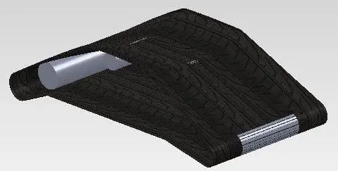
extrusion/cut and rays.
simple, fast and precise.... .
the parallel profile is nothing but a convert entity of the median one and with the addition of that part that generates the v form.
for the rest without driving curve, just give a direction and intensity to the fuchsia arrow of the loft...
?? I don't understand. But now you give me an example, don't you? :tongue:
apart from that reggio complicates life alone....the next step will be the movement in the environment together and its distinct.
You're learning to know him, huh?
...ah. But here you have fun teasing, huh? :wink:
Do the good guys or they're going after my swx's loser, all right?
 
impossible! we don't have that version...:biggrin::biggrin:
But come on, the nice game lasts little... It is necessary that sooner or later someone explain to him that his version of swx is an experimental weapon studied by the spectre to drive the enemy's designers mad and bring to collapse his industrial economy:tongue:
 
So you want your tape?
the fact with random measures not to waste time.
However, it is enough that the two profiles are of equal size.
 

Attachments

  • Nastro.webp
    Nastro.webp
    14.6 KB · Views: 21
So, I tried. In this case live edges emerge which could only be controlled by building the two external driving curves. I believe that the solution proposed by sampom is the fastest to achieve and similar to reality.
 
You're right, King....that of sam is the most correct one.
I haven't lost more than 10 minutes.
I opened the reggio file and after 5 minutes of disconcerting, I figured out how it was structured (some minutes) and then I made 2 surface functions. . Extrusion and loft.

for reggio
If you drive like models... you should take your license.
 
So you want your tape?
the fact with random measures not to waste time.
However, it is enough that the two profiles are of equal size.
...aaaahhhhhhhhhhhhhhhhhhhhhhhhhhhhhhhhhhhhhhhhhhhhhhhhhhhhhhhhhhhhhhhhhhhhhhhhhhhhhhhhhhhhhhhhhhhhhhhhhhhhhhhhhhhhhhhhhhhhhhhhhhhhhhhhhhhhhhhhhhhhhhhhhhhhhhhhhhhhhhhhhhhhhhhhhhhhhhhhhhhhhhhhhhhhhhhhhhhhhhhhhhhhhhhhhhhhhhhhhhhhhhhhhhhhhhhhhhhhhhhhhhhhhhhhhhhh ? ? ! ! !
mail the file, the file for piety [2010 possibilmente, la 2011 x ora l'ho solo a casa]
..the così?View attachment 18398 Hello
marco
It looks so cool! Now I try to interpret and reproduce on my true dis,
But one thing will be different: I miss the connection between part of the horizontal roller and the conical one inclined.. I mean, I'm gonna miss the surface to lean on. . .

formatted the pc and return.. :
 
...aaaahhhhhhhhhhhhhhhhhhhhhhhhhhhhhhhhhhhhhhhhhhhhhhhhhhhhhhhhhhhhhhhhhhhhhhhhhhhhhhhhhhhhhhhhhhhhhhhhhhhhhhhhhhhhhhhhhhhhhhhhhhhhhhhhhhhhhhhhhhhhhhhhhhhhhhhhhhhhhhhhhhhhhhhhhhhhhhhhhhhhhhhhhhhhhhhhhhhhhhhhhhhhhhhhhhhhhhhhhhhhhhhhhhhhhhhhhhhhhhhhhhhhhhhhhhhh ? ? ! ! !
mail the file, the file for piety [2010 possibilmente, la 2011 x ora l'ho solo a casa]It looks so cool! Now I try to interpret and reproduce on my true dis,
But one thing will be different: I miss the connection between part of the horizontal roller and the conical one inclined.. I mean, I'm gonna miss the surface to lean on. . .

formatted the pc and return.. :
I'm sorry, but I have 2011 and the file deleted it after samp posted the most real one.
 

Forum statistics

Threads
44,997
Messages
339,767
Members
4
Latest member
ibt

Members online

No members online now.
Back
Top