utente6
Guest
Good morning, everyone.
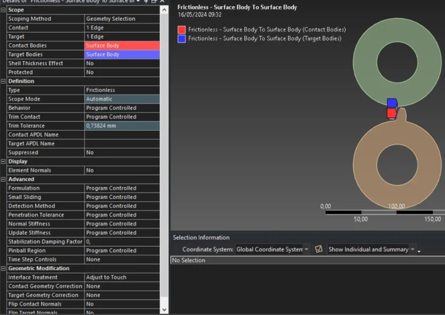
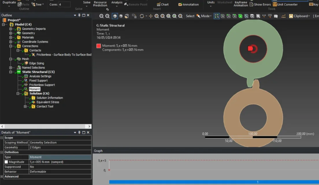
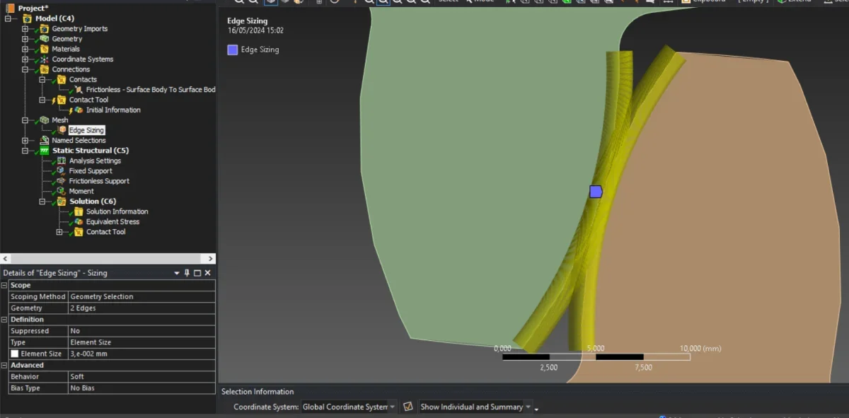
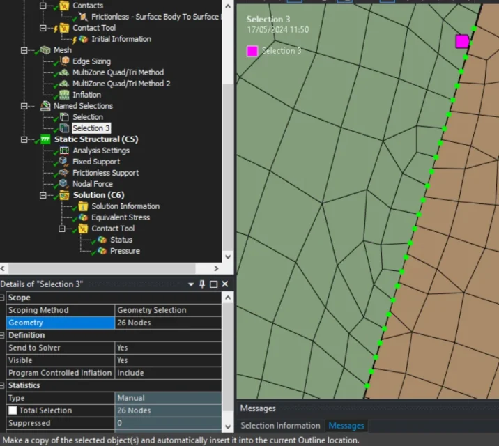
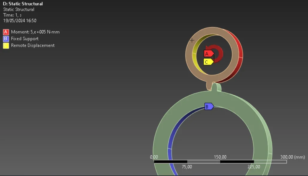
I would like to ask for help with a problem that I am experiencing with ansys student (it is the first time I use it so I am still a beginner). I have to study the contact between two teeth with hertz theory, in particular the maximum pressure that is exerted on the contact ellipse, the problem is that between simulation and analytical calculation the results are too different (theoretical analytical calculation pmax=664 mpa, ansys max=26mpa), but I can't well understand why. in the simulation, in 2d, I'm assuming I have only one tooth in the socket. I hope someone can help me, please.
I would like to ask for help with a problem that I am experiencing with ansys student (it is the first time I use it so I am still a beginner). I have to study the contact between two teeth with hertz theory, in particular the maximum pressure that is exerted on the contact ellipse, the problem is that between simulation and analytical calculation the results are too different (theoretical analytical calculation pmax=664 mpa, ansys
max=26mpa), but I can't well understand why. in the simulation, in 2d, I'm assuming I have only one tooth in the socket. I hope someone can help me, please.