• This forum is the machine-generated translation of www.cad3d.it/forum1 - the Italian design community. Several terms are not translated correctly.

how do i really estimate the size of the most suitable screw?

  • Thread starter Thread starter Ghio
  • Start date Start date

Ghio

Guest
Good evening to all,
I am happy to hear you:)

I searched in the forum and found only very in-depth topics that seem to me little to do with the very simple thing that interests me.

My boss often asks me to use smaller screws than I thought, but I would like you not to get too small. . .

I carry an example, from table a screw m6 8.8 resists before starting the yield to: 16.100 * 0.8 = 12880n = 1312kg.
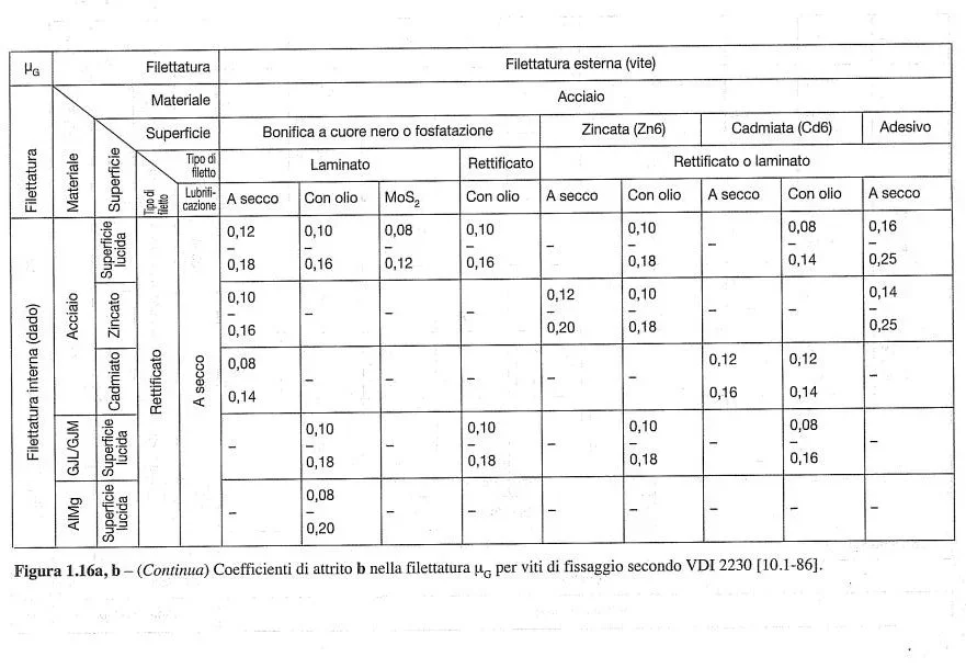
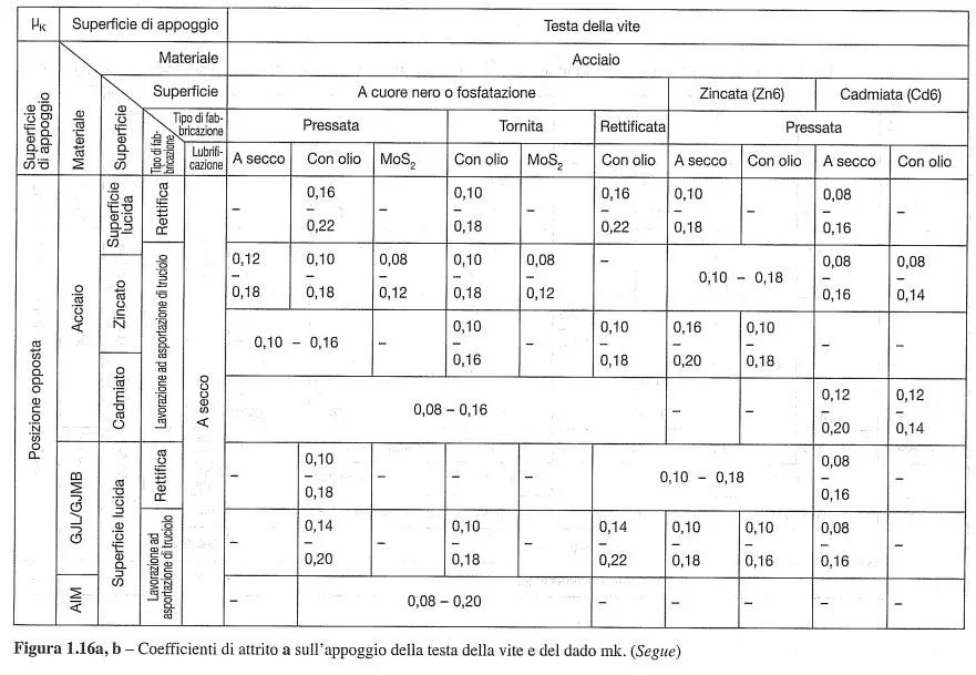
I attach the table used.

Wow! Can I really use only m6 screws?
something suggests to stop the initial enthusiasm. . .

Is there a more or less fixed percentage that I can generally keep values calculated in such a way to ensure a proper hold?

I wrote in the student forum because I think it is a basic and very useful thing to others too.

Thank you.
 

Attachments

I can tell you a few things:
- the correct approach of verification and sizing of bullionatire should be made according to norms at least uni en iso 1993-1-8 or according to vdi 2230. so you need to use coefficients and check materials....depending on heavy loads on bolting
- practical approach, risky is to take the breaking load to tabulate traction and use it to 60% ....or make the relationship between load and breaking load and have a value greater than 1. I repeat, dangerous, spannometric, to be compared with the stresses that undergoes and above all a mother-in-law who is able to carry the load of the screw.
 
I have found these tables of vdi 2230 that I attach for friction coefficients, according to you are those that need or are there others?

from the previous discussion that I was advised I reworked the underlying method for the estimate of the size of the screw and the number of screws, can it be a useful simplification both for the loaded screw axially (object connected for example to the ceiling) and radially (object attached for example to the wall)?

only examples to intuitively understand the layout, we actually do not work with ceilings and walls, but with components almost exclusively in steel.

a perplexity that comes to me and if the friction coefficient changes in the two axial and radial cases,

However, the method I used to say:

the friction force does have to be:
fa = p * k, where k is the safety factor (attrite)

the force f of traction of the vines, which generates it will be
f = fa / mu, where mu is the coefficient of friction

dividing f for the number of screws

I find the vine whose section resistant equivalent 'a' (from tables) is such that: sigmay = f* k' / a, where sigmay is the yielding sigma and k' is the safety factor (for yielding)
 

Attachments

  • Attrito della filettatura.webp
    Attrito della filettatura.webp
    59.4 KB · Views: 19
  • Attrito su appoggio testa vite e dado.webp
    Attrito su appoggio testa vite e dado.webp
    67.2 KB · Views: 17
how much confusion in all this.
we start clarifying some things:
- the friction coefficient can be hypothesized but will be in function of the lubrication of the screw or braking present. if the plates are dry and clean or if they are greased. there are several discussions on the forum where you talked about values and conditions. the tables you have attached can be a guideline but the practical side is the real one
- as far as the load capacity of a tensile screw does not depend on how much the pull. if you test with galdabini you will get breakage for failure of the resistant diameter.
- if you apply a screw and make it work traction, you will have according to uni en iso 1993-1-8[math]ft,rd=\frac{k_2•f_{ub}•as}{\gamma _{m2}}[/math] and therefore for screws not washed you will have [math]ft,rd=\frac{0,9•f_{ub}•as}{1,25}[/math] where as is traction resistant area, fub is the traction breaking load.
- if the bolting does not have to be preloaded controlled, the screws close anyway up to a maximum of[math]fp,cd=\frac{0,7•f_{ub}•as}{\gamma _{m7}}[/math] where the coefficient to denominator is 1,1.
- if the jute has to resist friction, the norm establishes that recroaching, cutting and friction checks are met.

There's nothing to invent. the norm speaks clear.

This is the mirror.
screenshot_20211216_223414-jpg.64112
 
Thank you. @meccanicamg 🙂

to " resist friction" do you mean object attached to a sloped wall and therefore the screws are subjected to effort at least partially radial?

However, we in the company for our applications, all steel on steel, we have always considered tensile strength increasing the size of the screw simply to verify that the object is on... Then it came to my mind to deepen.

Therefore, having never done so, I do not think that for such applications we have the obligation to legally show compliance with regulations.
or should it always be done?

from here this my question: whether in the case of axial effort, or of radial effort the resistance of the screw (by hindering therefore the other components) can I estimate it quite well leaving the check to cut?

I ask, because so I already know how to realize a little better for my practical situation.
Of course in the time-cuttings I also deepen from me the topic on the huge Eurocode 3 and the book of the neumann.

Thank you.
 
Last edited:
when you grind two plates together and apply a perpendicular force to the screws, there is the friction force that keeps the plates firm. it is due to the traction force of the vines multiplied the coefficient of friction. when you overcome this force, the screws will be cut. after which the crash.

once you make an excel sheet with formulas I would say it becomes all simpler and immediate to evaluate.

any unregulated method is risky. or you know what you are doing or is catastrophic.

You're drinking to go deeper, but there's a lot of winemakers out there who'd better close up to give way to the professionals.
 
Thank you. @meccanicamg for all advice,

In fact, I am still relatively new as a designer and recently in this company, thinking about the screws I have treated, unlike what seen here in other discussions, they all work axially to simply keep the weight, apart from some very light cover tanks, very much is welded. . .
and there is a different story e

However, still out of curiosity, a hanging body attached to the wall (so it does not move), since gravity is present, it is also considered subject to friction regarding the resistance of the screw, right?
if the screws are horizontal and vertical gravity, the plate with the wall has an friction. that is evaluated.
 

Forum statistics

Threads
44,997
Messages
339,767
Members
4
Latest member
ibt

Members online

No members online now.
Back
Top