• This forum is the machine-generated translation of www.cad3d.it/forum1 - the Italian design community. Several terms are not translated correctly.

how to make sheet fun?

  • Thread starter Thread starter volaff
  • Start date Start date
I made it a little too easy.
I was wrong to use edge for straight parts where instead it should be used edge-flangia that manages in addition to the bending radius also the height
instead for the curved parts after the edge function you can make a simple extrusion as long as it is not united to the body and therefore constructively will be welded parts (if you want you can do with base flange also these, then you can get the development; but a function for curved tract must be done)
I finally had a good time doing comb mating.
View attachment Assieme2.zip
 
I'm looking at the file and that sheet can never spread that depression can't be integrated into the sheet; as you did it you can only build for molding. If this is the way you chose it is fine, but then you make a pile of useless pippes with the history of development that at most would only woven the hips.
If you want to make it as a folded sheet, I suggest another way to make a single body (excluding the depression that would be soldered later). i.e. eliminating the base flanges and making the edges without radiated parts that instead add after with the edge command.
Be careful that here solid I think is wrong in succeeding in developing, because a curve cannot bend it if not around its axis. But let's close an eye.
All right, I had a good time playing games. . .
View attachment 46389
In fact, that depression went backwards (the sheet had to be put on the outside side).
I better explain the story now that I have 5 minutes.

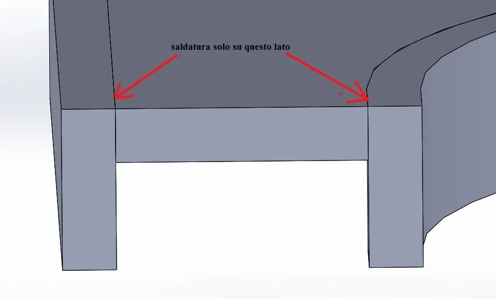
in practice that plate (corpi 2 and 3) (prova.zip) must go to clamp a tube (the one we talked about in the other discussion) and it was decided to make the two plates first to comb (idea to be evaluated) and then like those in figure (leaving a space to be used to realize a welding between bodies 2,3 and body 1.

Of course, it is appropriate to avoid going to empty at the side of the junction radius to avoid concentration of tensions.

what I was wondering is: but with a funnel (on the opposite side than that I rushed before) it is possible to make this piece (the original one is more or less equal with the embutitura on the right side) for sheet bending or can it be done only for molding? ? ?

I think I understand.

I thank you for the availability and for helping me to understand a little better the strategy that you can use to shape a sheet metal part favoring the flattened escaping.


Of course.
 

Attachments

  • lastscan.webp
    lastscan.webp
    86.7 KB · Views: 2
on the funnel are unprepared, but if something changes between doing it before and after I would say that there can be a change of form; if you make the fun first, maybe when you bend the shape, or if you first fold when you enter, you deform the side parts. . I honestly have no idea. I think they depend very much on the thickness, size of the detail, pressure to do the two jobs... You engineers' stuff! consider that part of the shape ends beyond the side fold and I don't think it's a nice thing to do (see picture)
why not think to divide the part in this way: the bottom with its funnel made with a press with the mold and two side banks made with folded and soldered sheet externally (see 2 image)Immagine.webpImmagine.webp
 
Thank you very much.
the idea can be good.
We'll see.
basically central part imbuted and side folds welded.

Thank you again.
Say hi.

fly
ps: Am I wrong or in your set the mirrored parts overlap for a certain stretch and then the sun cuts are made one plate and then on the other?
would no longer make sense to make, for example, the whole full side (where you used the edge flange command) and then make the cuts (as you did together) but directly on the part file?
 
the axieme is done to the good more for fun than anything.
the idea would have been to make the mirror as the original configuration so that you can manage the propagation of the cutting functions (expensing or activating in the original configuration and in the mirrored one). Unfortunately, it does not create the configuration of mirroring in the parts containing plates, it seems to me that it is a limit solved in the successive versions, then propagating the cutting functions in the original would be extended also to the mirroring*. as I wanted to do a parametric thing I chose this road even if a little wild.
* one way would be to bypass the thing and it would be to open the mirrored part and fill the cuts derived from the original, but at the moment I didn't want to bang so much. the fact that they overlap is a desired choice because if you have to frame and work with subtraction of material on the assembling this extra material there must be; if you notice the curved parts that do not hinge are all equal; a small improvement to avoid reasoning is to create the mirroring plane corresponding to one of the curved traits instead of offset of one of the straight traits, in this way whatever the height of the straight traits when I go to make the cuts will always fit perfectly
 
We're good morning.

I did something a little wild.
to avoid "foring" where there are variations of curvature came out is what.

Let's see.

Thanks again soon:)

ps: I made it really wild and, to get it out of sheet metal, I think I will have to shape it in a different way, remaining you can see the fun.
Maybe someone more experienced in funnel will give us some good suggestions.
Who knows!

:
 

Attachments

  • Immagine.webp
    Immagine.webp
    104.3 KB · Views: 6
pps: since I have to create a kind of comb structure I remember once a post of axioms and derivatives in which updating one part the other does it automatically. Do you remember or do you know where I could find him?
Thank you.

with the search function by user (marcof seems to have created the post) did not come out snatch.
 
Good morning and good Sunday.
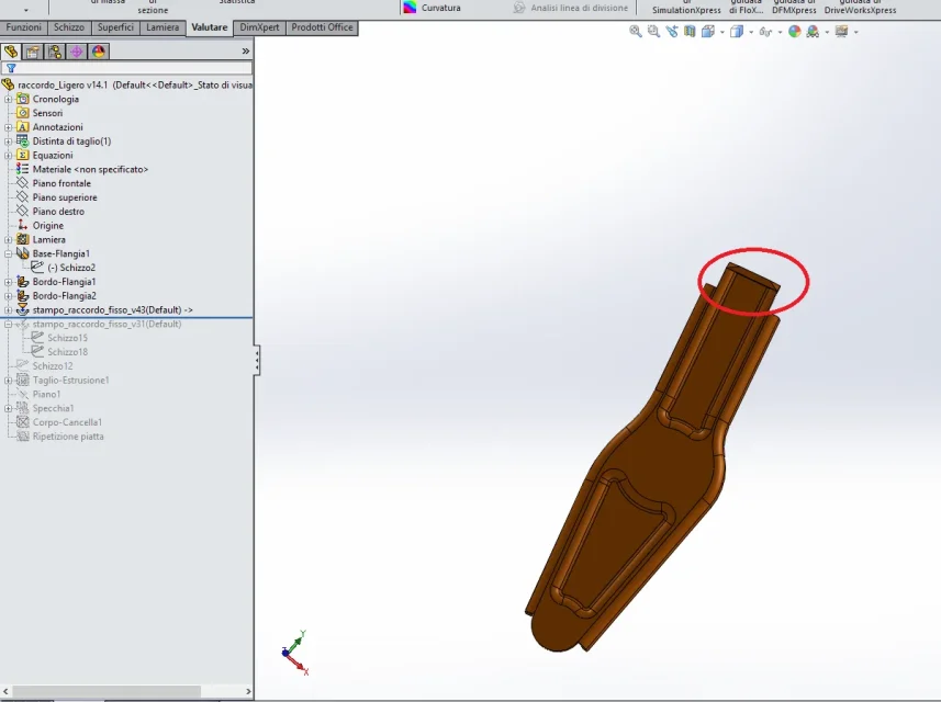
I have a part in sheet metal (picture 1) of which I would like to extend the imbuted part (circled in black) until the end of the piece; only that in my case (picture 2) when I enter I get the piece of image 4.

I realized this punch (picture 2) only that I did not understand how to do what I would like (maybe I should insert something in the forming tool but I did not understand how).

brutally I could extend the figure and then cut but I would like to do something more correct and educational.

Does anyone know how I could solve this?

thanks to all and good Sunday.
 

Attachments

  • Immagine1.webp
    Immagine1.webp
    59.1 KB · Views: 4
  • Immagine4.webp
    Immagine4.webp
    57.6 KB · Views: 3
  • Immagine2.webp
    Immagine2.webp
    52.7 KB · Views: 3

Forum statistics

Threads
44,997
Messages
339,767
Members
4
Latest member
ibt

Members online

No members online now.
Back
Top