• This forum is the machine-generated translation of www.cad3d.it/forum1 - the Italian design community. Several terms are not translated correctly.

i ask for help on the assembly function

  • Thread starter Thread starter Teopado89
  • Start date Start date

Teopado89

Guest
Hello I have a file with two leotards.

a sent by the customer, and a modeled by me (to make some increases in thickness, I made offsets of the original surfaces, closed geometry and converted surfaces into solid).
now I find these two solids (original, and material that should be added to the original).

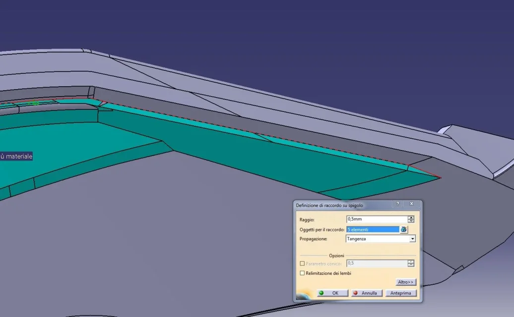
I can't assemble them in one solid. It gives me error on the tangent edges highlighted, but I can't see such edges and therefore identify the error.

I'll get you the file.http://www.filedropper.com/problemaassemblyCan you create a single solid? Thank you very much
 
sometimes in reporting errors, the graphics mess up, it is enough to request the update of the command that gave error and you see it highlighted in red.

another system to better highlight the edges in error is to give preview of the command (union in this case).

if you are struggling to track it, make the bigger model transparent, or work with wireframe display

attention that solved the error visible to the first instance, then there are no others and in your case it is probable, as the solids you have made have several non-clean and non-conciliating zones, so the system (which is sketchy) is messed up.

to solve it on the fly, translating 0.02 mm the solid matteo thickness according to a normal volume average, so that it slightly sinks into the original luca solid.

the solution is not elegant, but it works, otherwise you have to do the job with a different setting.

Let me know if you still want help.

Hi.
gianni thank you so much, you solved my problem: I moved the piece of 0.015mm and it works.

I had found on the internet a similar solution (that is, it was aimed at making the two solids connect) giving thickness to one of the two, but as you saw the surfaces are not simple and also there it made me mistake.

Thank you!

I wanted to ask you:
how to do it "require the update of the command that gave error and reveal it highlighted in red. "
"another system to better highlight the edges in error is to give preview of the command (union in this case). " I made preview in the assemble or join command but nothing happens, I don't know
"attention that solved the error visible to the first instance, then there are no others, and in your case it is probable, as the solids you have made have different non-cleaning and non-binding areas, so the system (which is sketchy) is messed up. "So if I understood correctly I should do as you say to view the first mistake, then I put it in place, and then I raise the command and see the second mistake and so on until I fix everything, right?

Thanks again
 
1) question: when there is a mistake, the feature remains unresolved (complete an exclamation point on yellow background) and giving the whole i.e. turning it down (ctrl+u) the system reworks the features by blocking on the unresolved one and showing you the error.

2) question: I do not think anything happens, the error has to give it and it is definitely visible, but it is very small: just enlarge it (look well, it would be that red point) and you should see it even when you give the preview command (or you have problems with the graphics card).

3) question: yes, view the first error, correct it, then step to the second etc.

the suggestion to give the thickness is valid, but your faces of the solid fall into each other, so it does not work.. .


in your case it also works the method of using only the external surface of your thickness (prisma slices: select the surface, limit option/up to the next element, giving as direction a normal average to the volumes)

let's say that before starting in fourth to make the thickness, better analyze the starting volumes and correct the upstream flaws.
 

Attachments

  • 1.webp
    1.webp
    33.5 KB · Views: 3
Thanks again gianni, now I try as you say with the prisma function.

I was trying another way this morning:
as you see in the attached file, between the original piece and "matteo thickeners" there are stupid rays that bother.
then I created a surface "cut the original piece" to remove them.
to create it I extracted the surfaces of the original piece and extrapolated to get them out of the solid.
despite this, he didn't cut.
then I sank this 0.008mm cutting surface into the solid and cut it off.
then I wanted to add these 0.008mm to the piece (it is a delicate part, where it makes punzone and matrix closure), and then I extracted the grounded surfaces, and I made an extrusion of 0.008mm in the opposite direction of the previous cutting operation.
a logic rigor I should have restored the original geometry without the stupid rays.

the question is:
How come if I take the original piece and the piece with the changes mentioned in the rows above, in wireframe display do not coincide?
is it a graphic problem or did I make any mistakes?

in the file you find a geometric "close" group that highlights the area I'm talking about. The two solids don't match.

Thank you for your help.
Matteo
http://www.filedropper.com/assembly2
 
Thanks again gianni, now I try as you say with the prisma function.http://www.filedropper.com/assembly2
I remind you that it's an approximation to make it quick "to the target," if you mess it up. . .
then I wanted to add these 0.008mm to the piece (it is a delicate part, where it makes punzone and matrix closure), and then I extracted the grounded surfaces, and I made an extrusion of 0.008mm in the opposite direction of the previous cutting operation.
a logic rigor I should have restored the original geometry without the stupid rays.http://www.filedropper.com/assembly2
It is not so... extrusion creates an exact geometry in the direction set, instead the original geometry is composed of extrapolations in tangency or continuity oriented according to the base surfaces, or by fittings and differently oriented surfaces: It can't work exactly! and in fact it is not...

I predict that the best way to work on solids is chunky, but the original solid obtained from the step is not great, and understand how it was made to modify it by working with sweep, coast and groove could be complicated so you have to arrange.

try to limit your field of action to radius and counter-rage, without extending too much.
If you want to follow your system, try to extract the tangent surface to the radius, the extrapolation that goes beyond the counter-roaring of what you need, seems to me 1.5 mm, without joining it only uses extrapolation, then select the surface and do the extrusion in the direction, trying to cut the solid, it should work.

or I think it's better:
extract from the original solid all the complete surface (multiple extraction/point continuity)
then extract the curves of the radius, counterrage following all the contour (fallo in 4 extracts)
join the 4 draws (which encircle all beam surfaces and counterrades to be eliminated)
cut the full surface with the union of the 4 draws (the hole on which you work to build the new complements remains right)
do the complements (if you have to extend the field of action, better not do it directly on the big surface, but extract a curve with which you cut the surface and then work on that)
join the whole
close the surface in solid

some advice:

1) Never assign red color to an entity, red by cat is the color with which it signals that the element is not updated and errors (if you do not see them), and avoids green and orange for the same reasons.

2) when you need to overlay maths to analyze differences, in addition to using different colors (here you can use green and red only temporarily), assign to one the continuous line and to the other the dotted line, and display only wireframe: you will be much easier to understand where they are equal (continuous line but dotted red-green:equal, only red or only green: addition or absence of volumes between versions.

3) works parametric and shootmetry at the end (if you just care about it)

4) file name and number always equal part

5) always works in a product (1 part the original, the other your model)

Hi.
 
Thank you for all your precious advice.
If I can, to add some further "scratch" to the possibilities to "get out" from these "fast" situations but that often happens, especially working with files made by customers/suppliers, I add:
1) creating the solid "prism" instead of using a sketch plan and then extruding it by limiting it to the surface, you can (of course if the surfaces have a minimum of strip compared to the direction you want to give ) directly extruding the surface by placing it in the command instead of the sketch. This allows you to create a solid exactly with the edge of the surface you already have.
2) to save time, if you have many non-contiguous surfaces, you can, however, use the join (meaning me) and disable the contact check box . This way if you have 10 "pitchals" you can extrude them with a single command . sometimes some surface (especially if it comes from iges or other) could be "inverted" . In this case you have to make inserts/operations/ ... should be reversed or similar. and then remake the join by replacing the original surface with that "turned".
3) together with the union command there is the healing command that allows to "adjust" the surfaces, within a certain tolerance, by tangency and, I think, by curvature.
4) in cases where you have few curves and comparable values, it could be useful, instead of "woman" immediately with join/offset/etc. try to reconstruct the surface with a multisection . the purists of the surfaces make to shiver , but if you create a grid with 5 or more parallel sections of the surface that you want to reconstruct and two always derived guides from the surface , having care to apply to each section the command to simplify the curves (I don't remember the name, it's next to the join) , continuous ' curvature, box selected for simplified Italian type (or as it remains).
This is also a simplification, so it should be evaluated by case.

I hope I have helped and not created confusion.
 
a clarification: in my previous suggestion I considered to remove some surface, but in your case that you have many, extracting all the contour becomes too long and boring...so to do first and without bumping do so:

extract from the original solid all the complete surface (multiple extraction/point continuity)
multiple extraction/no propagation, selection of all beam surfaces and counter-rage you want to remake (first image)
edge (of multiple extraction performed)
cut the full surface with the edge (the hole on which you work to build the new complements) (according to image)
do the complements (if you have to extend the field of action, better not do it directly on the big surface, but extract a curve with which you cut the surface and then work on that)
join the whole
close the surface in solid

This system can be used for a single surface (to remove and remake those surfaces to "caramella", twisted or serrated) or for so many as you need, avoiding selecting edges at times very jagged and difficult to follow.
 

Attachments

  • 1.webp
    1.webp
    84 KB · Views: 1
  • 2.webp
    2.webp
    66.5 KB · Views: 1
Thank you very much for your help.
I did!
:4460:
I followed the indication of an expatriate reader for the prisma function, so as to fix small empty spaces that had created me translating my solid thickness into the original piece (to ensure the assembly of solids).

However, this solution created a bad geometry in the radius area and counter-rage (my solid was sinking and covered half-range).
then I cut the original surface as gianni55 said, closed the geometry in some way (then it goes covered by my solid thickness), and I used the prism function on the faces of my solid to "enlarge" it and then ensure a little interference with the original model, and in fact the assembly went to the first blow.

Now I wanted to add the rays and counterrades to the final model, and it gives me the following error:
1.webpWhat is it?

Thank you very much.

p.s. I attach the "our" masterpiece: http://www.filedropper.com/assemblytogliendoiraggi
 
Good August!
waiting for years
the problem seems the vertical edge right of the red edge.
as usual I can't open the files, so I'm just on the pictures.
could "help":
1) try to select, in case you haven't already done it, even the edge after what from the problem . with these geometries sometimes the software can't understand on which edge to continue with the radius;
2) test, the "remove face" to eliminate all the "small surfaces" that can annoy and then apply the radius;
3) if you think of sliding the "main" radius, try also to complete first all the rays on which the radius should flow. Sometimes it helps simplify calculation.
Congratulations to you and gianni.
 
Now I wanted to add the rays and counterrades to the final model, and it gives me the following error:

What is it?
Hi.
the system tries to run the radius, but fails, as it is found in the presence of several problems: non-linear edges, but with micro strawberries (you only see if you enlarge a lot), surfaces with too rough variations between them etc., which eventually result in an excess of difficult situations to manage/simplify for the system etc.

these problems arise from many causes:
offset from already problematic surfaces (from conversions)
forcing joints of surfaces not in tangency/continuity
presence of many small closure patches
And so on...

as rightly said expat reader, however take what comes from the customer/supplier and try to arrange.

you can make some effort to simplify the areas where the radius is planted and proceed to radiate:

fig. 1.2.3 simplifies zones
fig 4 radius 0.5 arresting you before the end of the edge (the rest calculates it him)
fig 5 radius 0.5 selections all edge

the result is not nice, and you have to solve some corners, but if you want a better result you have to make at least one part of the job.

If you can't, send me to an mp your email that I send you the model (only until morning, then I'm in the mountains).

Let me know.
 

Attachments

  • 1.webp
    1.webp
    49.6 KB · Views: 2
  • 3.webp
    3.webp
    77.4 KB · Views: 1
  • 4.webp
    4.webp
    66.1 KB · Views: 2
  • 5.webp
    5.webp
    65 KB · Views: 2
  • 2.webp
    2.webp
    53.1 KB · Views: 1

Forum statistics

Threads
44,997
Messages
339,767
Members
4
Latest member
ibt

Members online

No members online now.
Back
Top