• This forum is the machine-generated translation of www.cad3d.it/forum1 - the Italian design community. Several terms are not translated correctly.

injection moulding component

  • Thread starter Thread starter picc
  • Start date Start date

picc

Guest
hello to all
I do not know if it is the appropriate section, in case of negative response I will move the discussion to the right topics. I have to simulate the injection molding process of a component for a project at university. the component is that present in the attachments (I uploaded only the main views but obviously I have the cad file). for simulations we are using visi-flow software and we have explained the basic commands.
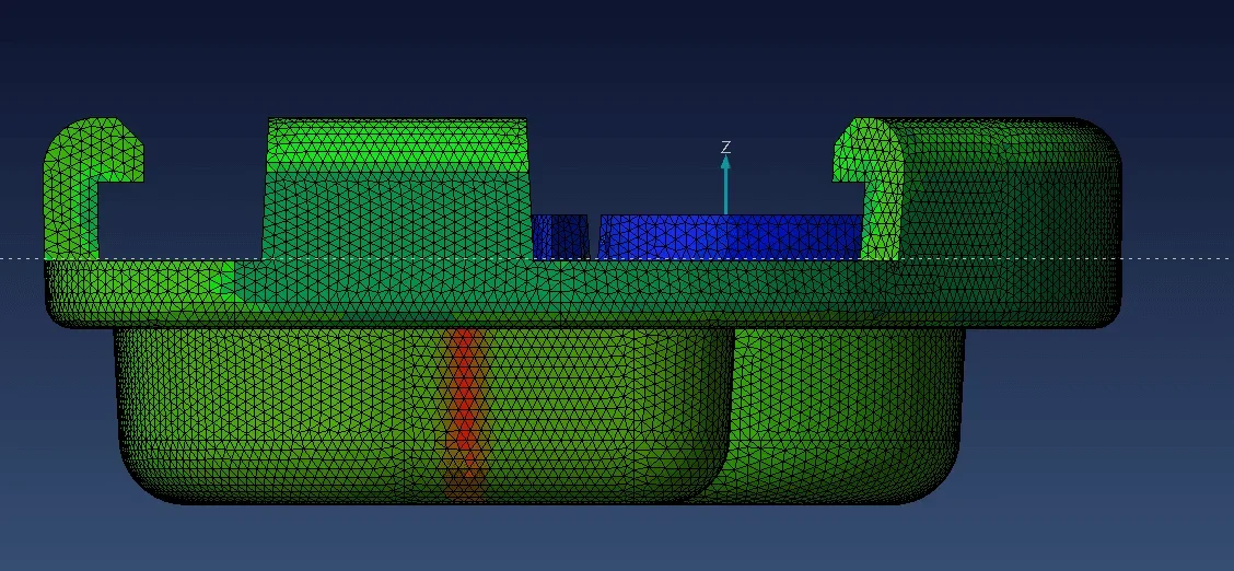
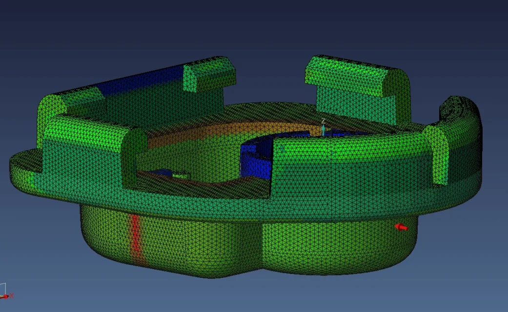
the first step I made was to run mesh on the component and already here I have a doubt: Once the mesh is done, we have been told to correct the calculation of the thicknesses running the software. doubt is related to the fact that I'm not sure what the software did. For example, the circle that is seen from the view from the bottom should not be there (if I have understood well how it calculates the thicknesses the program) because if the red circle should be there then a half arc should be present due to the semicircle that is seen from the view from the top.
the other great doubt that I have is the choice of the injection point, as I do not know where to place it since the first simulations I did (chosing as an injection point that shown in figure by the red arrow) did not show significant variations of parameters such as cutting effort, temperature, solidified sheath etc to vary the position of the injection point. where should the injection point be placed?
Thank you very much for the attention!
 

Attachments

  • mesh isometrica.webp
    mesh isometrica.webp
    342.2 KB · Views: 20
  • mesh laterale destro.webp
    mesh laterale destro.webp
    156.7 KB · Views: 21
  • mesh laterale sinistro.webp
    mesh laterale sinistro.webp
    148.4 KB · Views: 17
  • mesh punto di iniezione.webp
    mesh punto di iniezione.webp
    214.7 KB · Views: 16
  • mesh vista da dietro.webp
    mesh vista da dietro.webp
    164.3 KB · Views: 16
  • mesh vista da sopra.webp
    mesh vista da sopra.webp
    337.5 KB · Views: 13
  • mesh vista da sotto.webp
    mesh vista da sotto.webp
    260.6 KB · Views: 11
  • mesh vista frontale.webp
    mesh vista frontale.webp
    169.2 KB · Views: 10
I can tell you that what you have chosen is the last place where I would inject such a particular, which is far from simple.
first of all with all those subsquadri the side of the tabs to l will be by force of things the mobile part of the mold, with its carts.
it goes by itself that the injection will be fixed, then on the top of the dome. depending on the aesthetic and mechanical needs of the piece you can have, perhaps, some options, but I would say that the most accurate injection will be placed on the flat part of the dome, more or less in the center.
 
hello technomodel! thanks for the answer! Can I ask why the point I choose is so wrong? for the not unidirectionality of the flow? then for the mold I'm not sure that I realized that you mean, we had thought to do so, taking cue from video of the tube where cover for smartphones were made: the mold for the side of the fixed dome, then two other parts of the mold (on the die side) instead mobile, so that you can manually extract the cover!
 
Injecting at that point would create very tortuous material flows and different lengths, moreover the flow front would be much longer than injecting at the center of the dome, increasing the problems arising from cooling of the front, junction lines, flow turbulence etc.
As far as the mold is concerned, you would hardly be able to extract a particular hand-made one. I'm evaluating to the eye not having size to give a precise judgment, but it seems to me to see that those fins have a consistent thickness, which would prevent him from flexing in order to extract the piece. In addition, such a molding would be uneconomic, requiring an operator to significantly increase the cost of the piece.
in addition to this, a set of things should be evaluated before being able to reason and set the mold. First of all, the material with which it would be printed, the finishing of the piece and then of the imprint, the annual production and the various batches of production, the tolerances required for the finished piece, any functional/esthetical constraints that prevent the placement of injection points and extractors in certain areas etc.
 
ciao @picc , I may be introductory not so much on molding issues but on a functional question: Those curved hooks don't even bend to hammer. . .
 
then the component is very small:
20x20.2x7.2 mm^3 (smaller than a coin of 1 euro as a surface) then the hooks to l have very small thickness, if I don't remember badly less than 1 mm. for this reason we thought they could bend!
the material with which they are made is the pe (generic, viscosity we should choose it, but we will probably choose one with low viscosity). Finally, the annual production required is 240.000 pieces.
the problem is that if not individual the injection point is useless to continue with additional simulations, where various flow rate, mold temperature and material etc., to reduce cutting efforts and temperature, which are the biggest problems!
another doubt I have is on the material: once solidified the pe is flexible (type cover of the smartphone)?
try to inject on the flat part of the dome, in my opinion at the center of the circular ribs you have below.
alternatively to the center of the piece. Of course, if you have no constraints.
the pe will not be flexible, or better, it will be according to the thickness.
but those hooks will tire to flet and return to position to block the due.
thanks technomodel, cmq a simulation with the default parameters with the injection point you specified we have already made it. tomorrow there is reception with the professor and let us clarify these doubts that we have! thank you so much again!
 
hi, the detail you represented in the image, so to the eye, it seems a little "thankful" to be injection molded. try to eliminate the subsquadri that you do in this way really complicate your life. I leave you a link where you can find ideas about it. (on the net there are many others, but the concepts are always the same)
the thickness of the particular must be uniform, the sforms are decisive for this. once created the detail by eliminating all "useless" subsquadri and having uniformed the thicknesses you can switch to the filling simulation phase.
to verify that the thicknesses are uniform do not need special software, do sections and observe .
I would also put the injection point in the center to detail if you use a hot room system,
 
thanks technomodel, cmq a simulation with the default parameters with the injection point you specified we have already made it. tomorrow there is reception with the professor and let us clarify these doubts that we have! thank you so much again!
If you can, I'd like to know what the professor thinks.
 
hi, to answer your questions correctly, I should have the 3d model of the piece,
and see all the thicknesses and subsquadri, determine the division line. perhaps changing
the material and increasing the sforms you could attempt a tear extraction of the subsquadra if they are small.
 
per @tecnomodel Today we talked to the professor! he said that with regard to the mold, the inner part (the most critical we say) should be realized by means of a mould that "glussa" so that you can extract the piece: i.e. the mold part where there are subframes must yield so that they can be removed. In the end we did not dwell much on this point since we were not required to design the mold, but only to determine the best conditions for molding. as regards the starting point instead said that a possible point could be the lateral one where the thickness is greater (in the mesh image seen from behind the area concerned is the one on the right (or left) thicker then in green lit), however on the opposite side of the dome for needs of the mold. this because you will have to use cold power channels.@simone omi Your emails I cannot change the geometry or the material of the component! on the material I can decide the degree of viscosity density, but I can't change it! cmq the piece is very small, and the subsquadri have size less than the millimeter.
 
per @tecnomodel Today we talked to the professor! he said that with regard to the mold, the inner part (the most critical we say) should be realized by means of a mould that "glussa" so that you can extract the piece: i.e. the mold part where there are subframes must yield so that they can be removed. In the end we did not dwell much on this point since we were not required to design the mold, but only to determine the best conditions for molding. as regards the starting point instead said that a possible point could be the lateral one where the thickness is greater (in the mesh image seen from behind the area concerned is the one on the right (or left) thicker then in green lit), however on the opposite side of the dome for needs of the mold. this because you will have to use cold power channels.@simone omi Your emails I cannot change the geometry or the material of the component! on the material I can decide the degree of viscosity density, but I can't change it! cmq the piece is very small, and the subsquadri have size less than the millimeter.
a collapsing mold I never heard of it: eek:.
However, in order to be able to move those subsquadro sectors you can use inclined inserts, or create a cart that runs to eliminate the subsquadro.
I don't understand how it could yield a piece of mold, since in the center it can't be empty.
injection point chapter:
if injected into the thickest part means that you will find the front of the material that has already partially cooled that has to fill the narrowest area, you will have an increase of pressure.
the area where it tells you to inject is not the best, but given the size of the piece you could get a good result the same.
on the fact that you have to use cold channels I don't see why you have to inject in the part below, you can well inject in the center of the dome by making cold channels, just make a mold with third plate and a small matezza that will feed the various footprints in the center of the dome.
 
As for the mold, not being the goal of the course (there is another special course) we have not deepened so much, it was more a curiosity/doubt that we had me and my project partner (although a minimum obviously should be imagined how the mold should be, otherwise it would be possible to inject from any point).
for the injection point now I have a doubt: is it not recommended to inject where the thickness is greater (if possible) and so that the flow is as smooth and balanced as possible?
first of all a piece that must be printed must have as uniform thickness as possible, so already for this your statement has not much foundation.
What do you mean by balanced flow? balances the straightness, or the hot channel, so you have uniformity between the various footprints. the flow that fills the piece would not consider it balanced, unless you have more injection points, in that case the flows must be equal to each other.
 
sisi the piece is better if it has uniform thicknesses definitely, but for example I think of the joystick of the playstation where some parts are less thick (for example near the analogues, I don't know if you have present) and I think that this pieces are injection molded. In other words, with thicker parts, I was referring to the fact of injecting where the thickness of the generic component is greater.
with balanced flow I mean that it follows a path as homogeneous as possible and that it does not have many direction changes (as little as possible).
 
here is precisely the departure that is wrong.... search the best point to feed a piece, without having the slightest idea of how to make the possible mold
 
here is precisely the departure that is wrong.... search the best point to feed a piece, without having the slightest idea of how to make the possible mold
I agree, though only partially.
I always play first of all on where it is possible to inject, evaluating the needs of the piece and the needs of the mold, then I try to reason on how to build the mold in order to inject at that point.
if it becomes impossible or very expensive I make a series of evaluations, even with the customer, and I go to look for an injection point that allows me an acceptable compromise between finished piece, mold cost, realization times etc.
Of course, the basis of all this is that it is necessary to know how to build it 'this blessed mold, if not to end to a mere simulation exercise that however does not lead to anything, in case the mold is not feasible.
 
the point here is that the piece as it is designed is not feasible, the subsquadra are on all 4 sides, in order to be able to print it, it is necessary to change the geometry in the subsquadra zones (create of the small openings in order to create small dowels in part fixed that crossing the piece go in mobile closure, creating the undersquadra teeth. This should be considered the production of 240.000 pieces a year, so at least 4 prints with hot chamber and 4 injection torpedoes. I wonder what criterion these people teach......(s)
 

Forum statistics

Threads
44,997
Messages
339,767
Members
4
Latest member
ibt

Members online

No members online now.
Back
Top