• This forum is the machine-generated translation of www.cad3d.it/forum1 - the Italian design community. Several terms are not translated correctly.

interface shell181 and only185

  • Thread starter Thread starter Mafranc
  • Start date Start date

Mafranc

Guest
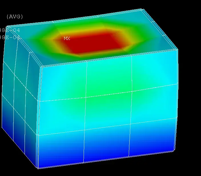
ansys 14 normal; My problem is the following. Imagine building a box with shells and filling it with solids. Of course the mesh did the same, the knots overlap and on the shell I stuck the rotations, but still my model does not work. How come? do you have ideas to solve without contact? Thank you
 
1-define your element type (181 and 185) and materials
2-create your box
3-as volume attributes (and only the I say volume) assigns the solid185 and its material.
4-like attributes of areas (and only areas) assigns et shell181 with its relative material.
5-generates volume mesh (vmesh)
6-generates mesh of areas (amesh)
 
I thank you for the info, but the results of my analysis are not credible, on one meter of my observatory I am moving 2600 meters.
I thought they might be probelmes of misutra units, but I think they are just; the settings e=210 000 000 ,ni=0.3 (module poisson).
I tried to set keyopt(1)=1 (blocking the shell rotations so that you only have spots to have the same degrees of solid freedom) and then also keyopt(3)=0 (on ansys terminal board) but without positive outcomes; also setting keyopt(3)=2 as recommended by ansys guide not by positive outcomes.
probably (I'm not a beginner with ansys) I have problems on edges, where the elements fail to convey tensions. Do you have ideas about this problem?
 
Good evening to all
I need help because I am doing the thesis in ansys and I need to know how shell 181 works, and which is the default coordinate system to understand how to orientate the layer of material, because I have to use this element for a composite material.
I also want to know what they need and what are the integration points.
I'd be very grateful because I don't know how to do it.
 
"extracted from a thesis on composite material"

in the library of ansys software was chosen the “shell 181” [16], suitable to meet the needs of modeling the case, i.e. a two-dimensional geometry that allows a response but above all the specification of a composite material.

figure 5 element shell 181 (ansys library)

as seen from the above figure, the element is defined by 4 knots (i,j,k,l) at the top of the quadrilateral and placed at the middle plane or at the top of a triangle, form the latter not recommended for a quality analysis. to each node are associated 6 degrees of freedom: the translations along the axes x, y, z and rotations around such axes. This element can be characterized by a section, like a real constant, in the specific case the shell section command has been used through which it is possible to define a maximum of 250 layers and to specify for each thickness, the material, the orientation of the layer regarding the x axis of the element and the number of integration points between the layers thicknesses (1,3,4,7 or 9). also well suited to use for single layer. the number of default integration points is three, one at the top, one at the bottom and one in the middle floor between the two. The 181 shell can be used for linear elastic, elastoplasty, hyperelastic, creep.. the section option, in the case of modeling from flat elements, allows to place the knots in the thickness as well as the top, bottom and on the middle plane, even at a generic distance from the modeled surface; all the section characteristics that will be specified, will have in this application the exclusive definition of the “middle plane”.
 
as described by stefano works everything.
if you place the input file is better.
 

Attachments

  • solid_shell.webp
    solid_shell.webp
    29.3 KB · Views: 4
so if I did not understand badly shell181 or shell281
work this way: I create a surface
any and then I make the various layers that will go
to compose the right composite material? but
what difference is there with solid layared always in matter of material
composite? thanks in advance :-)
 
However if you have some tutorials from which I can learn
to use the layared shell and layared solid there would be very grateful
because they are vital to me
 
Good evening to all
I have to use a solid layered 186 to define various layers of material.
My problem is that I can't figure out how to orient the azze z when I have a curved line as in my case(region beam) to be able to assign the thickness of the various layers.
 

Forum statistics

Threads
44,997
Messages
339,767
Members
4
Latest member
ibt

Members online

No members online now.
Back
Top