La Jolla
Guest
I beg to have done the good junior user and to have checked that there were no open threads on the same topic so I open one.
It's my first post, so I'll be prolished and bearded.
Good morning to all, I was wondering if someone had had like me pleasure, it is done to say, to use the new module "ifa" for the monodimensional modeling of inventor 2012. I use it as it is the only one made available to the technical office in which I carry out my internship, so the things are two: or I make it enough, or I make it enough!
to what I understand is a package born for the analysis of frames, but as a good almost mechanical engineer I am prodigal to exploit it as a generic monodimensional fem tool, in short, for the validation of the celeberrimi "simplifying models to rigid rods" that all of us mechanics love to flaunt, perhaps along with a beautiful frozen beer:biggrin:
I am curious to know what those who are using it think and what, possibly, will respond to my perplexity; but now I come to my experience.
my very first question:
if they have decided to insert a module for the analysis to beam elements, why insert it as superstructure (it must necessarily do the skeletral, then cotrure the frame with the appropriate function and then throw the ifa, so change section = exit and remake the frame) and not as simple beam analysis (we only disengage lines, we assemble materials loaded sections cannoli to the ricotta and launch the analysis)?
I find it unnecessarily complicated. Am I the only one?
a problem on which I clashed relates to the lcs (local coordinate system), which are literally put to the stern and perjunta are not editable from the inside of the ifa simulation, to put them in a way to display worthy results in terms of internal actions and efforts you have to exit and change the orientation of the solid elements of the frame!! (I then found that the lcs put them on the basis of the view in which we are at the moment when we insert the frame pieces, with the z axis always directed towards the summit closer to our "click", therefore I recommend to put them always "in front" and then when necessary turn them of k π/2).
another race lap. efforts and internal actions.
a praise deserves the fact that you can finally to see internal actions, even if the sign convention is all the contrary and there is no option to settle this.
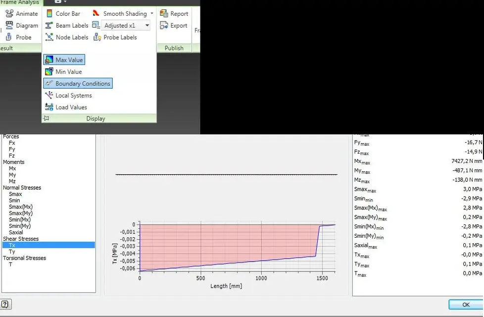
another thing I noticed is that...in the results there is no comparison stress! what the ifa calls "smax" (main- >smax resolutions) can deceive us, but nothing else is that the maximum axial effort, volgarmente sigma, calculated taking into account the flexing moments and the normal actions, but without taking into account the efforts of cutting, which can be seen precisely from the "cutting resolutions" or "torsio analysis".
This is to mean that among the results there is no solicitation of comparison...is especially in this regard that I hope to have taken a dazzle, would be a ridiculous lack (a rag of v.mises? )
last in order of importance but first in order of annoyance: I'll give you the cursed labels:
when a system is solved and we want to display internal actions\sforzi by diagram on structure 3d, two labels appear for rod, ugly and bulky and that often overlap, not to mention that when an action\sforzo is 0 (we understand, 10^-8/10^-12) it also marks it with a very showy label .
.
I hope I'm wrong here, but I couldn't eliminate them in any way. That's annoying.
in conclusion:
for those who understand me, I regret lusas to such a point that I regret the knots and put the fuchsia auctions.
in my opinion sin of maneuverability and customization; I see it very "blocked" and actually more suitable for simple analysis of frames, but maybe I have had too many expectations on a product that all in all is to its first version.
as we say in my parts: "Cunfusu cà pessuasu" (more confused than convinced)
It's my first post, so I'll be prolished and bearded.
Good morning to all, I was wondering if someone had had like me pleasure, it is done to say, to use the new module "ifa" for the monodimensional modeling of inventor 2012. I use it as it is the only one made available to the technical office in which I carry out my internship, so the things are two: or I make it enough, or I make it enough!
to what I understand is a package born for the analysis of frames, but as a good almost mechanical engineer I am prodigal to exploit it as a generic monodimensional fem tool, in short, for the validation of the celeberrimi "simplifying models to rigid rods" that all of us mechanics love to flaunt, perhaps along with a beautiful frozen beer:biggrin:
I am curious to know what those who are using it think and what, possibly, will respond to my perplexity; but now I come to my experience.
my very first question:
if they have decided to insert a module for the analysis to beam elements, why insert it as superstructure (it must necessarily do the skeletral, then cotrure the frame with the appropriate function and then throw the ifa, so change section = exit and remake the frame) and not as simple beam analysis (we only disengage lines, we assemble materials loaded sections cannoli to the ricotta and launch the analysis)?
I find it unnecessarily complicated. Am I the only one?
a problem on which I clashed relates to the lcs (local coordinate system), which are literally put to the stern and perjunta are not editable from the inside of the ifa simulation, to put them in a way to display worthy results in terms of internal actions and efforts you have to exit and change the orientation of the solid elements of the frame!! (I then found that the lcs put them on the basis of the view in which we are at the moment when we insert the frame pieces, with the z axis always directed towards the summit closer to our "click", therefore I recommend to put them always "in front" and then when necessary turn them of k π/2).
another race lap. efforts and internal actions.
a praise deserves the fact that you can finally to see internal actions, even if the sign convention is all the contrary and there is no option to settle this.
another thing I noticed is that...in the results there is no comparison stress! what the ifa calls "smax" (main- >smax resolutions) can deceive us, but nothing else is that the maximum axial effort, volgarmente sigma, calculated taking into account the flexing moments and the normal actions, but without taking into account the efforts of cutting, which can be seen precisely from the "cutting resolutions" or "torsio analysis".
This is to mean that among the results there is no solicitation of comparison...is especially in this regard that I hope to have taken a dazzle, would be a ridiculous lack (a rag of v.mises? )
last in order of importance but first in order of annoyance: I'll give you the cursed labels:
when a system is solved and we want to display internal actions\sforzi by diagram on structure 3d, two labels appear for rod, ugly and bulky and that often overlap, not to mention that when an action\sforzo is 0 (we understand, 10^-8/10^-12) it also marks it with a very showy label
.I hope I'm wrong here, but I couldn't eliminate them in any way. That's annoying.
in conclusion:
for those who understand me, I regret lusas to such a point that I regret the knots and put the fuchsia auctions.
in my opinion sin of maneuverability and customization; I see it very "blocked" and actually more suitable for simple analysis of frames, but maybe I have had too many expectations on a product that all in all is to its first version.
as we say in my parts: "Cunfusu cà pessuasu" (more confused than convinced)