• This forum is the machine-generated translation of www.cad3d.it/forum1 - the Italian design community. Several terms are not translated correctly.

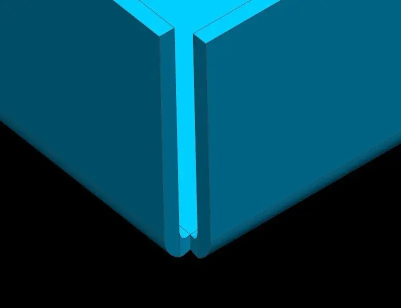
[lamiera] welded edges

  • Thread starter Thread starter Matteo
  • Start date Start date
mike uses the same method as mine and yours, and with the data detected it makes processing from the system integrated into the cad (and it is always the first to praise the features of swx), exactly like me and you.
simply establishes theoretical rays a priori, different from the real. Obviously based on these adjustments k to bring developments to the detected real dimensions.
mike doesn't use my method, if it's yours, I don't know.
the fold radius puts it almost to 0 and leaves it such if not explicitly requested by the customer.
does not use a real k factor, because if you use it in conjunction with a bend beam tending to 0, the development would be wrong.
formula :
angle * (pi / 180) * (fold radius + factor k * thickness)
How do you use a bend radius almost to 0 without altering the real k factor of the material?
 
the fold radius puts it almost to 0 and leaves it such if not explicitly requested by the customer. . .
the radius puts it to zero in "his design", the customer doesn't know that and he doesn't even care. clear that the finished piece will have consonant rays (real like mine and yours) and/or required by the customer.
does not use a real k factor, because if you use it in conjunction with a bend beam tending to 0, the development would be wrong.
are the first to say (but read well what we write?) that k and rays are not real, but "combined"(:biggrin:) together in formulas give him a real development. I have written several times that the k is "adjusted" according to its rays set.. In short; inverting the order of factors the result does not change:biggrin:. and when you send a shape to cut and then bend no one knows about your k, the important thing is that the dimensions are correct.

greetings
Marco:smile:
 
the radius puts it to zero in "his design", the customer doesn't know that and he doesn't even care. clear that the finished piece will have consonant rays (real like mine and yours) and/or required by the customer.

are the first to say (but read well what we write?) that k and rays are not real, but "combined"(:biggrin:) together in formulas give him a real development. I have written several times that the k is "adjusted" according to its rays set.. In short; inverting the order of factors the result does not change:biggrin:. and when you send a shape to cut and then bend no one knows about your k, the important thing is that the dimensions are correct.

greetings
Marco:smile:
beautiful to produce a piece not consistent with design or model 3d.
Do you?
Does anyone using 3D do that?

the mike method makes no sense to exist.
It's a beard and as such should not be recommended and adopted.
If he works with the cad so I can't do anything, he loses.
his method if he invented it not to lose the nights to understand how to set solidworks.
now it is found to create pieces of 3d sheet as if they were milled.
 
...piegator....being a low profile job, he thinks that for that kind of work you learn over time, devoting a person for a defined time.
I've been a 13-year-old folder and I don't think it's a low-profile job! It saddens me, but since you said it, you don't tange me!
For the record, I'm a certified mechanical expert with 50/60, so I'm not really a jerk... if I make the bending machine there's a reason! despite my profession in the small firm where I work I also designed an industrial hair dryer with solidworks and already made 2 supplies of 50 pieces and if you think that if I didn't do it (for so many reasons I'm not explaining) we would never have taken that contract..! for now I am satisfied so! clearly as a ppiegator and worker immersed in the workshop and in the problems I have built it to high study, without sampling and it has been exact since the first piece!:eek:
 
I found a bug:
the k factor value added to creation, is not possible editable.
to be precise there is the possibility to change it, but you have to act on the individual
bending by editing one to one value k.
bug solved with sp3, menomal :smile:
 
So many years of work, but education did not learn it, by the way, you have a horn punch r 0.05, perhaps to the nose.. .

or if not, bend 15 mm with a quarry of 35
 
hello if it can serve you again I modified your part.
ps. k = 0.5 but if you have a custom fold table remember to set it otherwise the development does not fit you...
 

Attachments

So many years of work, but education did not learn it, by the way, you have a horn punch r 0.05, perhaps to the nose.. .

or if not, bend 15 mm with a quarry of 35
Sorry, but who are you talking to? I think you can't talk about education because of your intervention.

and I remind you that as a new user before posting messages, you should read, put in place and respect this:http://www.cad3d.it/forum1/showthread.php?t=13677as from alerts you received in email and for pm.

then "go to the box" and then we can talk about education.

greetings
Mar
 
beautiful to produce a piece not consistent with design or model 3d.
Do you?
Does anyone using 3D do that?
As far as the plates are concerned, I do it!
I think you do too.
I'll explain. the notorious factor k and the formula for developments have linear trend, are simply geometric formulas. If you compare the experimental values with the calculated ones you will find that you arrive near it with folds at 90°; for different angles the stretching of the material does not follow the same law.
so if we want to be dotty, adopting an equal k factor for all corners of fold does not mean anything but to make a approximation!
the mike method makes no sense to exist.
It's a beard and as such should not be recommended and adopted.
If he works with the cad so I can't do anything, he loses.
his method if he invented it not to lose the nights to understand how to set solidworks.
now it is found to create pieces of 3d sheet as if they were milled.
beards are also used with the most performing cads in some circumstances: the plates are one of the cases in which they are forced, for the reasons mentioned above, to use particular escamotage, another example: how do you realize the discharges on the corner folds?
 
As far as the plates are concerned, I do it!
I think you do too.
I'll explain. the notorious factor k and the formula for developments have linear trend, are simply geometric formulas. If you compare the experimental values with the calculated ones you will find that you arrive near it with folds at 90°; for different angles the stretching of the material does not follow the same law.
so if we want to be dotty, adopting an equal k factor for all corners of fold does not mean anything but to make a approximation!


beards are also used with the most performing cads in some circumstances: the plates are one of the cases in which they are forced, for the reasons mentioned above, to use particular escamotage, another example: how do you realize the discharges on the corner folds?
solidworks can set automatically and dynamically, through a table (excel or txt), the corresponding factor k according to the fold and radius angle.

for downloads on corner folds, if you attach an image I can respond more clearly.
 
beards are also used with the most performing cads in some circumstances: the plates are one of the cases in which they are forced, for the reasons mentioned above, to use particular escamotage, another example: how do you realize the discharges on the corner folds?
and give with the performing cads.
Do you think that nx is more performing than sw? or more complete?
If you talk about performance, then I have my doubts, the engine is the same.
if you talk about completeness in modeling functions, there is no doubt.
I don't think so.
If you're talking about unbuted sheets, solidworks doesn't have the form.

in the cad I do not use beards.
what model is what should be, in all types of modeling (rounding, milling, moulding plastics or sand, etc.)
If the k factor does not produce me the correct flattening, we consult with the bending machine and we understand whether it is the k factor to vary shortly or why they did not use quarries and daffoons indicated.
from them or I change the table to add this case or I defer the design by putting the correct equipment used.
 
I am on the beach but I see it is hot also on the forum...
I did not understand the first intervention
the one about education and various dances.
would be desirable a public explanation
, considering that he wrote after months and after
My post.
Good we all. ;-)
 
and give with the performing cads.
Do you think that nx is more performing than sw? or more complete?
If you talk about performance, then I have my doubts, the engine is the same.
if you talk about completeness in modeling functions, there is no doubt.
I don't think so.
If you're talking about unbuted sheets, solidworks doesn't have the form.
some cars have the same engine but do not have the same performance. . .
I meant that, despite more or less complex commands, more or less complete, certain things cannot shape them as they come out of the production process. a typical example is that of the sheets where you have to make approximations. that they do by changing the k or the fold radius does not affect. if development is correct dimensionally as you get it does not matter to the bending machine.
I have developed formulas, in this area, that go to change the development according to experimental data: you can model the sheet with any radius (wanting) but the development remains that. It is obvious that in a 10/10 sheet I don't put a radius of 20, but e.g. I also modeled with infirm rays to get a well-kept coat. this is a beard because it leaves unchanged the development of the piece but slightly changes that of the lembi.

in the cad I do not use beards.
what model is what should be, in all types of modeling (rounding, milling, moulding plastics or sand, etc.)
If the k factor does not produce me the correct flattening, we consult with the bending machine and we understand whether it is the k factor to vary shortly or why they did not use quarries and daffoons indicated.
from them or I change the table to add this case or I defer the design by putting the correct equipment used.
I too for mechanical processing that do not predict deformations, model exactly what must go out, for example mold closures, but in some cases I have to make shaves. banal example: a 20 l=100 nominal diameter shaft rectified for the first 20 mm (changes only roughness). How do you represent him in modeling?
I put three pictures on the sheets:
the first concerns the finished product, the second developing it with the angle made in a certain way, the third with the angle made in another way. the real sheet will never be like that displayed at that point.
 

Attachments

  • 1.webp
    1.webp
    8.2 KB · Views: 9
  • 2.webp
    2.webp
    18.7 KB · Views: 5
  • 3.webp
    3.webp
    14.9 KB · Views: 6

Forum statistics

Threads
44,997
Messages
339,767
Members
4
Latest member
ibt

Members online

No members online now.
Back
Top