PiegatoreSolidworks
Guest
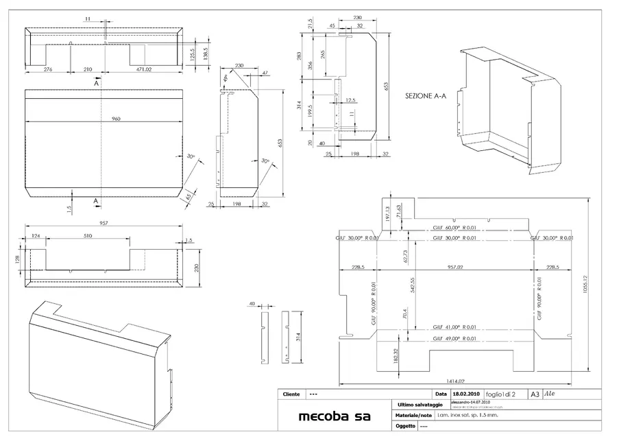
when I export dxf of my folded sheet I can export many things including geometry and fold lines...
is it possible that the fold lines automatically go under a layer different from the default 0? I do because otherwise I have to move them "handed" on a different layer. . .
Thank you.
is it possible that the fold lines automatically go under a layer different from the default 0? I do because otherwise I have to move them "handed" on a different layer. . .
Thank you.