Stefano-81
Guest
Hi, guys.
Since I often develop in 2d of the pyramidal trunk legs supporting reservoirs.
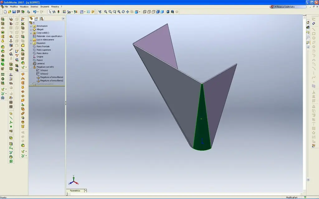
in free time I was trying to create 1 parametric model in 3d with solid work 2007 (see attachment)
I can't understand where I'm wrong.
I created my bending with loft
solid creates me solid
I don't know.
Is development right at this point?
thanks for the collaboration
Since I often develop in 2d of the pyramidal trunk legs supporting reservoirs.
in free time I was trying to create 1 parametric model in 3d with solid work 2007 (see attachment)
I can't understand where I'm wrong.
I created my bending with loft
solid creates me solid
I don't know.
Is development right at this point?
thanks for the collaboration

")