aguayo
Guest
Bye to all,
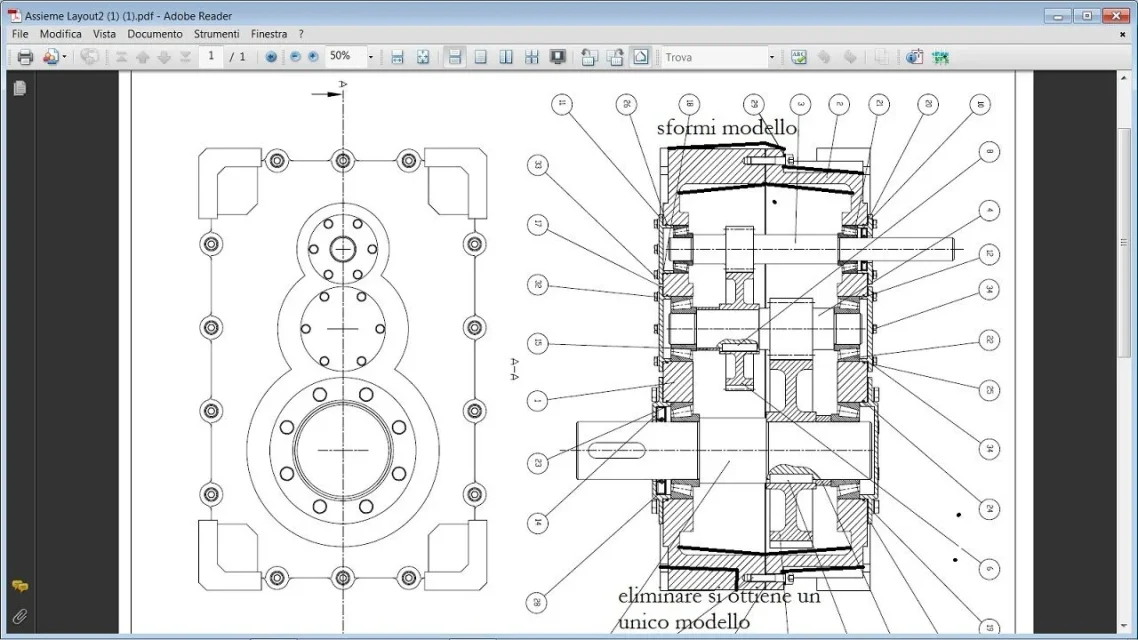
for the construction course there was assigned the sizing of a reducer (as tradition), the delivery date almost arrived. I have prepared a design of the aid but I have doubts and thought of "share them":
1) I would like to add pins of centering, where do they posiziono? Can I represent them with a partial section on the front view (the one where you see the plan perpendicular to the axes of the trees)?
2) the reducer will be lubricated to oil bath for which a stopper will be necessary for input and a stopper for discharge. same problem: where to place them? How do I represent them?
advice on other aspects are also accepted. more or less the reducer is 550 in height (just for an idea on the size), it is made with two shells cut into the perpendicular plane to the axes because otherwise, if cut into the other direction, there would be little room for the screws.
 )
)