• This forum is the machine-generated translation of www.cad3d.it/forum1 - the Italian design community. Several terms are not translated correctly.

multibody con nx

  • Thread starter Thread starter ceschi1959
  • Start date Start date

ceschi1959

Guest
hello to everyone, reading posts published on
creo/parametric ( http://www.cad3d.it/forum1/threads/50261-la-mia-opinione-su-creo-da-utente-catia )
Catia ( http://www.cad3d.it/forum1/threads/50094-dividere-un-solido-mantenendo-entrambe-le-parti )
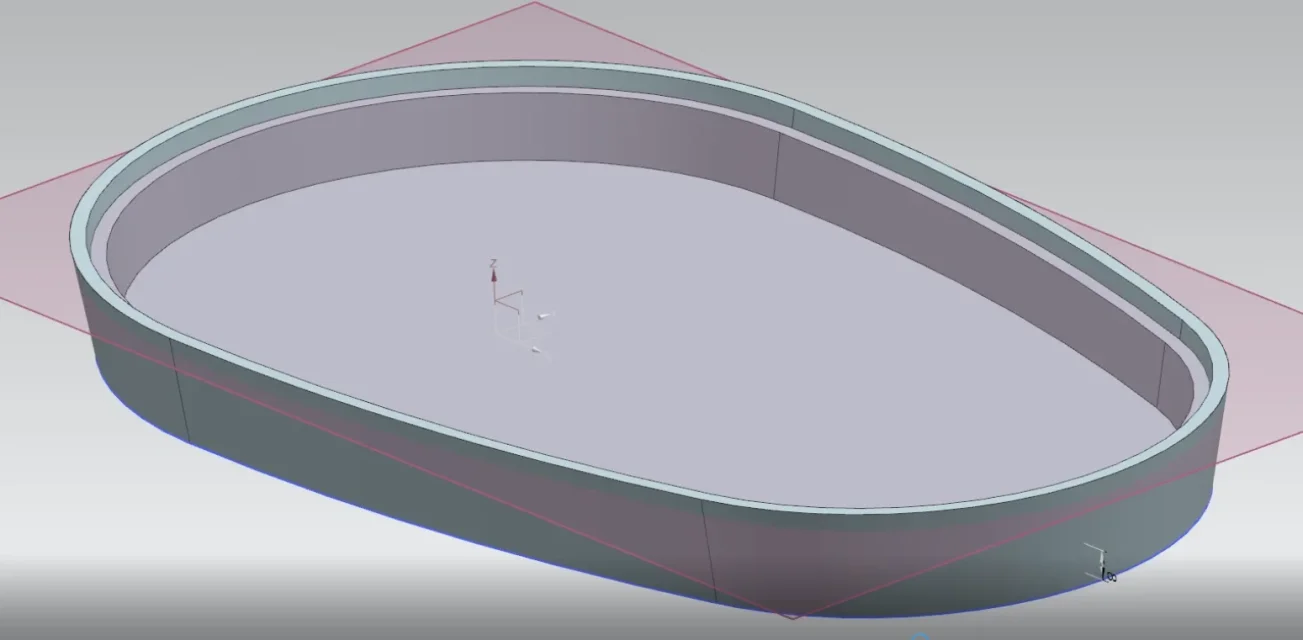
and others, I want to post a video of a buckle that I made a long time ago, I apologize because it is not very clear.
in it you see how I use the multibody by making tools that I go to subtract or add to the particular, I also divide the solid into two (maintaining the parameterity) to get the male and female of the buckle.
this is a discussion that I would like to share with all users in a serene and constructive exchange of experiences.
https://www.youtube.com/watch?v=auyans4wta8&list=flqljatb3sxjol91x_don8_w&index=1

ciao
 
hello to everyone, reading posts published on[/url]

ciao
I quickly watched the video and ask you a question:

What's the difference between using Boolean operations or normal excavation or protrusion operations, when the solids you use to add/subtract are made in the context of the part? I would better understand if the solids you use as tools were external parts of the file, making inter-part links, but so I miss the reason to use this methodology instead of classical.
There is a huge difference, thinks of working the tool, which goes to dig or add, with other operations. The latter are, for example, much faster in regeneration because they are made on a simpler geometry. The multibody is not only formed by solids generated by extrusions or revolutions, it can be constituted for example by face thickenings or copies of solids.
If I can place other examples to explain better.
No need, I understand....

I'm sorry, but I've got a little bit of a flaw due to the fact that you don't get past the turned and fried...
 
a beautiful modeling is nothing to say. to do the same work with creo I think it is necessary to model for surfaces. Instead, the video's multibody is all solid, right?
 
in it you see how I use the multibody by making tools that I go to subtract or add to the particular, I also divide the solid into two (maintaining the parameterity) to get the male and female of the buckle.
this is a discussion that I would like to share with all users in a serene and constructive exchange of experiences.
What do you mean here by making tools?
 
What do you mean here by making tools?
if you look at the two 'cilindri' that make the lateral discharges were made so:

extrusion of a circle
I split the cylindrical face with a midsurface (the upper and lower surfaces are not offset!!!)
the two sides so obtained
'mirrorized' the solid
subtracted

this is a very simple workmanship, others, which if I have time posting are on one side simple, on the other they allow you to do very complex things otherwise.
 
Yeah, I think I figured out the modeling process. the fact of calling them utensil is it because those geometries there would be the basis for the creation of tools like punches, molds etc... for the industrialization process?
 
to respond to calacc and hunter and to all those who wanted to confront a certain mode of modeling placed the following.

purpose of the 'project' is to create a tank that has certain characteristics as from image attached:

height to
thickness
hook teeth in the edge of thickness sp/2 and height 5

with nx I would have acted this way as you see in the movie:

creation of a sketch not necessarily shreddedcreation of a surface (bounded plane)
extrusion of the same (note how with nx can extruding everything, from edges to surfaces without needing to sketch... This is hybrid modeling)
thick shell tot
solid extraction (copy) before the shell (there is even a special command)
negative offset of the external surfaces of the solid extract equal to half the thickness from the shell
solid cut 5 height extract and subtraction

all operations that, in one way or another could have been simulated, non fare, with other cads, for example the border could have been carried out with a sweep but..... see after
at some point the customer changes his mind and oval shape wants to move to square shape:

reassociation solo the surface to the new sketch curves (and wanting also not), you control the sense of extrusion..... and it is all done because you exploit the variability as well as the parameterization.
https://www.youtube.com/watch?v=ax5y0rrl7kwp.s. is all parametric and ultra-associated does not even move with bombs!
 

Attachments

  • vaschetta.webp
    vaschetta.webp
    31.3 KB · Views: 6

Forum statistics

Threads
44,997
Messages
339,767
Members
4
Latest member
ibt

Members online

No members online now.
ciao
Back
Top