• This forum is the machine-generated translation of www.cad3d.it/forum1 - the Italian design community. Several terms are not translated correctly.

multisection surface

  • Thread starter Thread starter panormus
  • Start date Start date
point 6: I try to explain less cryptically.
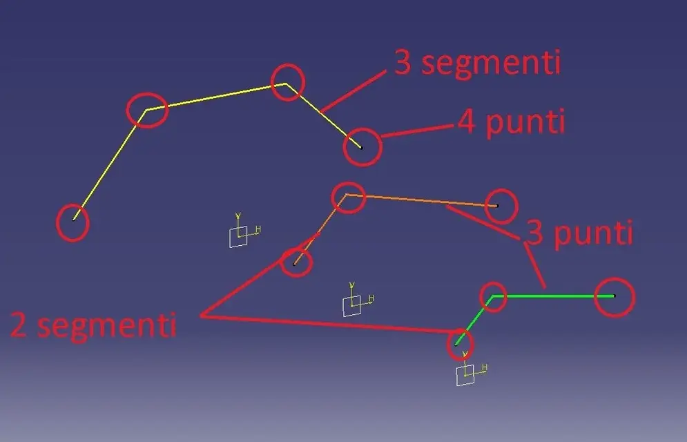
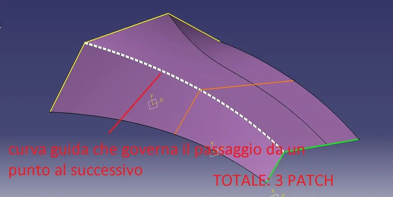
example: I have three sections with a number of unequal segments ( Edge-01.jpg image). if I make a multisection without further indication, the result is seen in edge-02, that is, catia must necessarily find a solution "uniforming" the number of sections (right segments - a edge passes in a random point of a segment of the orange and green sketchers); Moreover, without indicating a guide curve in the left segments each point (spigolo) generates an internal edge (and not governable individually) with the result of generating a unique surface consisting of 5 patches: a high number of patches does not involve problems (if not a useless complexity of the surface) until some fillet will struggle to run!
edge-03.jpg explains why it should also govern the internal curves.
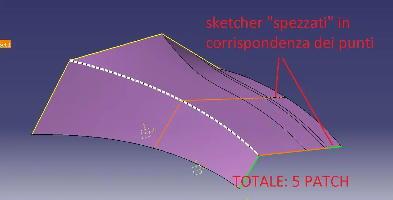
edge-04.jpg explains how (and why) it is advisable to have a number of homogeneous segments (the number of homogeneous segments is obtained by making the "break" of a segment within the membership sketcher)
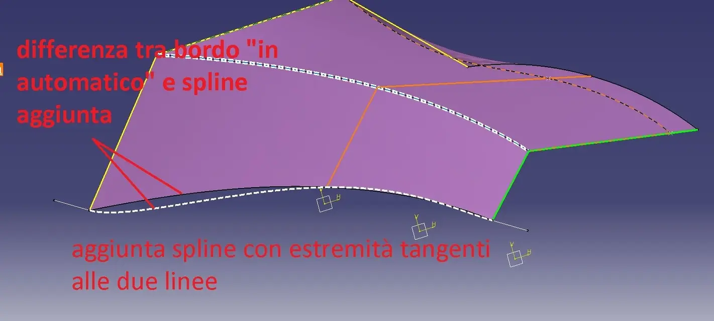
edge-05.jpg explains how to align the couplings (those that in images I called "points")
 

Attachments

  • edge-01.webp
    edge-01.webp
    25.7 KB · Views: 12
  • edge-02.webp
    edge-02.webp
    76.5 KB · Views: 14
  • edge-03.webp
    edge-03.webp
    42.1 KB · Views: 12
  • edge-04.webp
    edge-04.webp
    47 KB · Views: 11
  • edge-05.webp
    edge-05.webp
    75.1 KB · Views: 11
...continue

edge-06.jpg explains the difference between the automatic solution of the surface (board curve) and the possibility to govern the same with the desired curve
edge-07.jpg - final result
explaining to me is not my strong; I hope I've been clearer than before.

to view the file I should invoice you the performance: could cost you up to a maximum of 6 bottles of local wine:
2 inzolia,
2 cataracts
2 crushed
of course excellent producers!!! (well, not famous.. . )
 

Attachments

  • edge-06.webp
    edge-06.webp
    59.1 KB · Views: 9
  • edge-07.webp
    edge-07.webp
    65.2 KB · Views: 9
...continue
ima: it is modeled for 'subdivision surfaces', i.e. patch (or faces) that are in continuity of curvature. modeling the control points (mesh control points, not single patch) or changing the attenuation (or tension) of the edges to obtain a live edge (so seamlessly, neither tangency, nor curvature).
starting from a sphere or a cube is absolutely identical: the cube is a sphere with all the edges "attenuated" 100%.
However, for the product design, for cars (not class a) and for other non- strictly geometric shape components it is very good (on youtube there is a video of how they model an air duct of a motorcycle) .
for the aeromodellism even more!!!
starts like this:
- keep 'under' blueprints or curves of your model and insert a ball
- eliminates the face to the halfway (ima-1.jpg)
- press f4 and put yourself in side view.
- double click on the subdivsurf and its polygons appear
- Alt+key to the mouse make a trap including the points you want to move (alt+ctrl=multiselection)
- enlarge the extremes until you understand the maximum size and add a 'x' number of mesh lines (sections) by selecting a side edge where you want to increase the number (ima-2.jpg),
- always in side view, widens, lowers, stretches and moves until you approach the maximum form (ima-3.jpg)
- if necessary (and it is necessary!!!) add mesh lines in the front area to better define the 'naso' (ima-4.jpg)
- press f4, choose the view from above and repeat operations
- press f4 choose front view and repeat operations until you reach a detail level approximately close to the final form
and continue so until you reach the final form you like.
notes, comments, advice, or my way of working: probably not the best but I look good like this:
do not add all the mesh lines at first, add as you need it
works a lot with iso views (f4 is very comfortable)
work on the symmetry without worrying to keep the poles aligned on y0, on the contrary, go a little further (you will discover the symmetry in continuous curvature)
careful that when adding a (or more) mesh lines, change the shape then, always check
use subdivsurf as maximum surface: ima is integrated with gsd, so some areas you can solve with canonical surfaces without becoming mad with polygons
with f2 go to perspective view: is very comfortable to see the form "real"
Try all the icons you have on screen and find out what they do, then, try, try and try again: it's just a matter of "doing your hand"

...and with this you add me a 6 box of victory wax + original recipe of pasta with sarde (not those of tv!!!)

ps: good fun
 

Attachments

  • IMA-1.webp
    IMA-1.webp
    98.2 KB · Views: 11
  • IMA-2.webp
    IMA-2.webp
    44.6 KB · Views: 8
  • IMA-3.webp
    IMA-3.webp
    41.1 KB · Views: 9
  • IMA-4.webp
    IMA-4.webp
    26.5 KB · Views: 10
...continue
ima: it is modeled for 'subdivision surfaces', i.e. patch (or faces) that are in continuity of curvature. modeling the control points (mesh control points, not single patch) or changing the attenuation (or tension) of the edges to obtain a live edge (so seamlessly, neither tangency, nor curvature).
starting from a sphere or a cube is absolutely identical: the cube is a sphere with all the edges "attenuated" 100%.
However, for the product design, for cars (not class a) and for other non- strictly geometric shape components it is very good (on youtube there is a video of how they model an air duct of a motorcycle) .
for the aeromodellism even more!!!
starts like this:
- keep 'under' blueprints or curves of your model and insert a ball
- eliminates the face to the halfway (ima-1.jpg)
- press f4 and put yourself in side view.
- double click on the subdivsurf and its polygons appear
- Alt+key to the mouse make a trap including the points you want to move (alt+ctrl=multiselection)
- enlarge the extremes until you understand the maximum size and add a 'x' number of mesh lines (sections) by selecting a side edge where you want to increase the number (ima-2.jpg),
- always in side view, widens, lowers, stretches and moves until you approach the maximum form (ima-3.jpg)
- if necessary (and it is necessary!!!) add mesh lines in the front area to better define the 'naso' (ima-4.jpg)
- press f4, choose the view from above and repeat operations
- press f4 choose front view and repeat operations until you reach a detail level approximately close to the final form
and continue so until you reach the final form you like.
notes, comments, advice, or my way of working: probably not the best but I look good like this:
do not add all the mesh lines at first, add as you need it
works a lot with iso views (f4 is very comfortable)
work on the symmetry without worrying to keep the poles aligned on y0, on the contrary, go a little further (you will discover the symmetry in continuous curvature)
careful that when adding a (or more) mesh lines, change the shape then, always check
use subdivsurf as maximum surface: ima is integrated with gsd, so some areas you can solve with canonical surfaces without becoming mad with polygons
with f2 go to perspective view: is very comfortable to see the form "real"
Try all the icons you have on screen and find out what they do, then, try, try and try again: it's just a matter of "doing your hand"

...and with this you add me a 6 box of victory wax + original recipe of pasta with sarde (not those of tv!!!)

ps: good fun
And you could have talked before... from if you come to my house I offer you a nice lunch to you and your girl/wife including the good until.
Ima power is impressive. I managed to make the fuse quickly, but that will have to be treated more in detail.

I will spend more in detail.. or I will ask better:biggrin:
 

Attachments

  • fuso3.webp
    fuso3.webp
    208.9 KB · Views: 9
  • fuso4.webp
    fuso4.webp
    82.2 KB · Views: 8
...continue
ima:however, for the product design, for cars (not class a) and for other non- strictly geometric shape components is very good what is meant by product design and car class a?
(on youtube there is a video of how they model an air duct of a motorcycle) .I saw it, good work, but impossible for me for the simple fact that by pc I have a tractor.for the aeromodellism even more!!!
starts like this:
- keep 'under' blueprints or curves of your model and insert a ball
- eliminates the face to the halfway (ima-1.jpg)
- press f4 and put yourself in side view. f4- double-click the subdivsurf and appear its polygons (barre space? )
- Alt+key to the mouse make a trap including the points you want to move (alt+ctrl=multiselection)gives me a circle with written background and I can select a row of the proposed list.- enlarge the extremes until you understand the maximum size and add a 'x' number of mesh lines (sections) by selecting a side edge where you want to increase the number (ima-2.jpg),
- always in side view, widens, lowers, stretches and moves until you approach the maximum form (ima-3.jpg)
- if necessary (and it is necessary!!!) add mesh lines in the front area to better define the 'naso' (ima-4.jpg)
- press f4, choose the view from above and repeat operations
- press f4 choose front view and repeat operations until you reach a detail level approximately close to the final form
and continue so until you reach the final form you like.

:biggrin: wownotes, comments, advice, or my way of working: probably not the best but I look good like this:
do not add all the mesh lines at first, add as you need it
works a lot with iso views (f4 is very comfortable)
work on the symmetry without worrying about keeping the poles aligned on y0, on the contrary, go a little further (you will discover the symmetry in bending continuity)What? I also ask you: can I make two or more adjacent faces? and what we talk about continuity I ask you what difference is between g0.g1,g2 and g3.careful that when adding a (or more) mesh lines, change the shape then, always check
use subdivsurf as maximum surface: ima is integrated with gsd, so some areas you can solve with canonical surfaces without becoming mad with polygons
with f2 go to perspective view: is very comfortable to see the form "real"
Try all the icons you have on screen and find out what they do, then, try, try and try again: it's just a matter of "doing your hand"

...and with this you add me a 6 box of victory wax + original recipe of pasta with sarde (not those of tv!!!)

ps: good fun
Thank you.
I wait for you for lunch, as I say to ferretium, but separately so I sprinkle you:

just possible place other photos.
 
are impressive the sinuousness, cleanliness and speed of execution that can be achieved.
 

Attachments

  • fuso5.webp
    fuso5.webp
    88 KB · Views: 10
that means by product design and by car class a: by product design I mean all the objects that have an aesthetic value, such as: mouse, phone, mobile phone, lawnmower, hair dryer, coffee machine, chainsaw, shampoo bottle, helmet (bike, ski, etc.), etc., that is all those products that increasingly must be aesthetically pleasing (appreciated by the buyer) but that are not cars, motorcycles or planes.
class a: if you are looking in the forum there are great discussions. is a type of modeling (it is not a workbench!) where surfaces are created according to very high quality standards (g3+ methodology).
g0= point continuity (spigol)
g1= continuity of tangency
g2= bending continuity (up to second ctrl point)
g3= bending continuity (up to the third ctrl point)
- alt+tool button you make a trap including the points you want to move (alt+ctrl=multiselection) from a circle with written background and I can select a row of the proposed list. ---- Sorry ---- I have to correct, it is not alt but shift (or capital). alt serves to select hidden entities and not to make the trap as I told you.
 
and now let's go to the queue (last aid that then unfortunately I don't have much time available, maybe we take it back later).

method that you can also use for other parts of the model (the semiala? ).

tail-1.jpg: select the edges of the closing patch and bring the value of the 'attraction' up to 100 (frame in the middle to choose the edge and not curved attraction) - attention: In my opinion if you choose the edge option, it does not make sense a value other than 100, vice versa it is useful, and we will see it later, for the bending option.
tail-2.jpg: result
tail-3.jpg: 'extrusion' function to extrude starting from a patch (choose the last face as from edges highlighted in orange)
tail-4.jpg: stretches upward the upper face
tail-5.jpg: eliminates the internal patch (as for the initial ball)
 

Attachments

  • CODA-1.webp
    CODA-1.webp
    53 KB · Views: 6
  • CODA-2.webp
    CODA-2.webp
    25.6 KB · Views: 4
  • CODA-3.webp
    CODA-3.webp
    55 KB · Views: 4
  • CODA-4.webp
    CODA-4.webp
    26.8 KB · Views: 4
  • CODA-5.webp
    CODA-5.webp
    45.1 KB · Views: 4
...continue

tail-6.jpg: you will notice that extreme control points are not aligned, select them and choose the option in the pane; choose one of the two proposed floors (the vertical one)
queue-7.jpg: in two shots select and from 'attration' to the indicated edges; to the two higher from the value 75 to the lowest one 50 (so accompany the curvature towards that of the fuselage)
tail-8.jpg: rudder: add a cube, place it correctly and remove faces as from image
tail-9.jpg: do a xmm offset of what remains of the newly created cube
tail-10.jpg: subdivsurf split to get the two surfaces

You could follow the stess road to build the semiala or you could add a subdivsurf and then reconnect it with the fuselage, I would choose the second even if there are no substantial differences.

Have fun
 

Attachments

  • CODA-6.webp
    CODA-6.webp
    43.7 KB · Views: 5
  • CODA-7.webp
    CODA-7.webp
    41.8 KB · Views: 5
  • CODA-8.webp
    CODA-8.webp
    23.6 KB · Views: 4
  • CODA-9.webp
    CODA-9.webp
    77.9 KB · Views: 6
  • CODA-10.webp
    CODA-10.webp
    49.8 KB · Views: 4
Last edited by a moderator:
that means by product design and by car class a: by product design I mean all the objects that have an aesthetic value, such as: mouse, phone, mobile phone, lawnmower, hair dryer, coffee machine, chainsaw, shampoo bottle, helmet (bike, ski, etc.), etc., that is all those products that increasingly must be aesthetically pleasing (appreciated by the buyer) but that are not cars, motorcycles or planes.
class a: if you are looking in the forum there are great discussions. is a type of modeling (it is not a workbench!) where surfaces are created according to very high quality standards (g3+ methodology).
g0= point continuity (spigol)
g1= continuity of tangency
g2= bending continuity (up to second ctrl point)
g3= bending continuity (up to the third ctrl point)
- alt+tool button you make a trap including the points you want to move (alt+ctrl=multiselection) from a circle with written background and I can select a row of the proposed list. ---- Sorry ---- I have to correct, it is not alt but shift (or capital). alt serves to select hidden entities and not to make the trap as I told you.
for continuity of curvature do you mean concavity or convexity? or that flexo points are allowed? or anything?
to build aircraft in scale at what level should I attest?

So barlafus when are you coming to see me? :biggrin:
thanks for your very useful information :finger: that will also help those who did not assure you a lunch :wink:

Now I'd like to ask you: can I create a diagonal edge between the tops I choose and work on? For example, in the annex should I create that sort of triangular surface with at the base a living edge towards the inside of the fuselage?

(You know the planes well, don't you? )
 

Attachments

  • fuso9.webp
    fuso9.webp
    104.3 KB · Views: 5
we start from the end:
triangular surface on the fuselage with a edge: with ima does not agree, since then it must be tangent to the part relative to the cabin (if not mistaken). I would do it with free style: to edge and then impose the tangence on the centin of the cabin (try with the match surface, between fs and ima works).

curvature: by continuity I mean both in case of concave surface, and convex; the important thing is that both surfaces are congruent (both concave or convex). the flexo is admitted only if desired, otherwise the blow of light makes you unbearable crap. example of permissible flexo: inflating of the car wheel.
for an aircraft according to me the continuity that gives you ima is a lot. in case of complex areas you can also stop at tangence. It is not an aerodynamic problem, it is more related to the production process. If your piece is printed plastic, well, when it comes out of the mold it can also be very different from the shape of the model.

planes? I know only that they go quickly from one point to one point b, incredibly without touching the ground, and that the hostesses are medium nice.
 
we start from the end:
triangular surface on the fuselage with a edge: with ima does not agree, since then it must be tangent to the part relative to the cabin (if not mistaken). I would do it with free style: to edge and then impose the tangence on the centin of the cabin (try with the match surface, between fs and ima works).so can I cut a face from the ima surface and connect it to a surface made with fs? I intend to do so the tail plan because in your way it is not very simple, but the cut with the surface of the rudder was a nice straight.curvature: by continuity I mean both in case of concave surface, and convex; the important thing is that both surfaces are congruent (both concave or convex). the flexo is admitted only if desired, otherwise the blow of light makes you unbearable crap. example of permissible flexo: inflating of the car wheel.
for an aircraft according to me the continuity that gives you ima is a lot. in case of complex areas you can also stop at tangence. It is not an aerodynamic problem, it is more related to the production process. If your piece is printed plastic, well, when it comes out of the mold it can also be very different from the shape of the model.Would that be different? What do you mean then? but it will not be plastic, but all in wood. important will be the care of the design to realize well the ordered (among the many other things), the ladder for the whole model and properly position currents and the surface in balsa. (but not before an ongoing piper, which I momentarily suspended to loosen design stress, I was going crazy, but I wanted to learn how to work better with surfaces). planes? I know only that they go quickly from one point to one point b, incredibly without touching the ground, and that the hostesses are medium nice.:rolleys: non ci credo minimamente :tongue:
how do you analyze the created surface so that you don't predict for example flaws, drafts (if so you can call) and make it uniform? I hope I'm explained.
 
is there any way to ensure that the curve generated by an intersection between surfaces becomes manageable as they were patch curves?

or do you think it is better to cut the surface of the fuse into two parts, tighten the famous triangle and then add patches and collect them?

The second one seems hard.
 

Attachments

  • fuso11.webp
    fuso11.webp
    61.7 KB · Views: 2
"is there any way to ensure that the curve generated by an intersection between surfaces becomes manageable as they were patch curves?"No.
"or do you think it is better to cut the surface of the fuse into two parts, tighten the famous triangle and then add patches and collect them? "It's hard work, but it's the only road to follow.

analyze the surface:
the two options I use most are: cutting planes and analysis of the "zebra lines" (you understand the term "zebra" from the image...). I don't know what license you have, but if you have ima, you should also have these possibilities of analysis.
the first allows you to make one or more sections by orienting them as you prefer (try to make an infinite number of sections 10mm apart and see the result; Moreover, for each section, you can view the trend of its curvature (see image 'sections.jpg')
the second makes you look like 'the curve trend' by displaying on the model of black and white bundles (which you can customize). is judged the trend more or less "pleasant" of white and black.
the development of zebras should be judged among the various patches: if between a patch and the neighbor the white curve does not break or does not espgolo then it is good, on the contrary it shows an imperfection (which can sometimes be desired)
in the image zebra.jpg I indicated with 'ok' the good trend of some lines and with 'ko' the "broken" trend; where I have indicated ko we have forced edges, quinids, in that area, zebras will never be beautiful.
do some tests change the parameters and see the various results.
Good job
 

Attachments

  • sezioni.webp
    sezioni.webp
    124.7 KB · Views: 6
  • Zebra.webp
    Zebra.webp
    87.9 KB · Views: 6
always precious, thank you now I have a picture I think enough to be able to work.
I tried the first and I laid the pc for 20 minutes... I have a tractor. :Mad: I will shortly try the second.

in the meantime I want to share with the community a method that I am using to realize the fuse while not having the intermediate orders (who would find this info for the tecnam p2002 jf please contact me): the method is to create in fs of the 3d curves that run the profile on all 3 dimensions to have an idea of the shape to reach and project these curves on the ima surface which will have to be worked properly until the projection on the surface coincides with the 3d curve of origin. :mixed:
 

Attachments

  • fuso18.webp
    fuso18.webp
    45.5 KB · Views: 7
  • fuso19.webp
    fuso19.webp
    91.1 KB · Views: 7
  • fuso20.webp
    fuso20.webp
    43.3 KB · Views: 7

Forum statistics

Threads
44,997
Messages
339,767
Members
4
Latest member
ibt

Members online

No members online now.
Back
Top