PiegatoreSolidworks
Guest
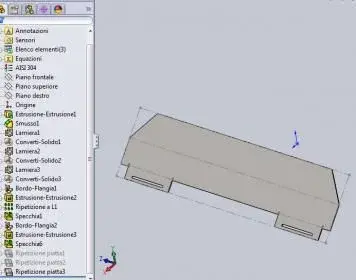
I tried 2011 and came across a "problem": I tried the new function of the plate flange mirror and it works but only if used once! if I apply it on the usual file on a second sheet visually works but in reality does not "explain" the result....
question: is it a bug or something normal?
question: is it a bug or something normal?