• This forum is the machine-generated translation of www.cad3d.it/forum1 - the Italian design community. Several terms are not translated correctly.

oblique extruded cut

  • Thread starter Thread starter Liuk_17
  • Start date Start date

Liuk_17

Guest
hi to all, I am new to the forum and I write to you to ask some indications about some features of solidworks 2017.
I have to make an oblique extruded cut, tilted about 45 degrees, on a cylindrical surface.
I know how the plan is made to make the sketch and then the cut, but how do I cut it obliquely?

I looked a bit in the forum through advanced research but I couldn't find anything.

Thank you.
 
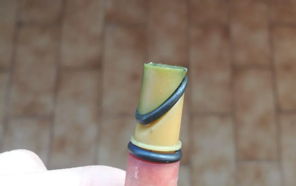
to the eye I would say giving him the parameter of direction, but without a caspita of image or a pen sketch is really a solution randomly thrown
 
I attach an image of the cut that I have to do
photo_2018-02-10_15-32-50.webpif needed I can also send the sketch in solid
 
eh bhé give immediately the 3d removes phatos to the request.. .
is it because you have to make a whole mess when you just build a tilted plane and draw the cut sketch?
However, the first proposed solution is also good
 
the problem is that I can't make a tilted plan ...I don't know what the function to use or the controls, I only know how to parallel them to the main planes (frontal, upper and right)
 
then do not plan and stay on the first solution.
other solution is a sweep cut.
 
the problem is that I can't make a tilted plan ...I don't know what the function to use or the controls, I only know how to parallel them to the main planes (frontal, upper and right)
If you don't know how to do the tilting plans, you have to learn how to do them because it is indispensable. :smile:
you can't look for alternative solutions because you don't know the commands.
you need simple reference geometry appropriately positioned so that the cad can have all the references they need to create the plan. You could put yourself on the side floor, draw a 45° tilted line and use it to make the plan by selecting the final point of the line and the line itself. there will be twenty other different methods and the most comfortable depends on the 3d model you have underhand.
 
I did so, intersecting a horizontal plane created with the main right plan.
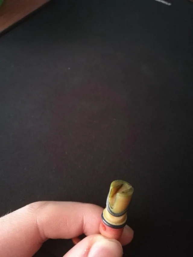
I have a second question. How do I perform an oblique o-ring seat?
I know that there is the toolbox for the locations, is the oblique plan always used?
photo_2018-02-11_16-47-47.webp
 

Forum statistics

Threads
44,997
Messages
339,767
Members
4
Latest member
ibt

Members online

No members online now.
Back
Top