• This forum is the machine-generated translation of www.cad3d.it/forum1 - the Italian design community. Several terms are not translated correctly.

orthogonal axle reducer (output conical couple)

Mattia0608

Guest
I'm a high school boy who has given me the complete design of a gearbox (from material choice, bearings, wheels, etc.) .
My problem arises a bit in doing the initial draft, in fact today I have proposed a sketch to my professor but he has “buddled” me saying that I can do better in order to present a more interesting project.
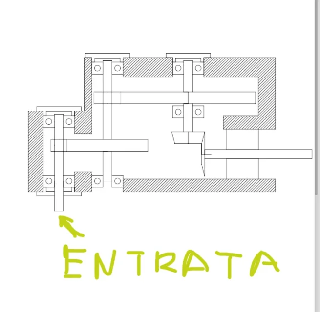
This is the sketch with more or less realistic general encumbrances I have done, there are so many things like the right bearings, blockings and all the things that arise.
Let me know maybe how I could improve or if you have a set that could help me to take some inspiration (on the forum I looked a lot but with outgoing conical couple I found nothing, in case I missed it I apologize and I will delete the post).
 

Attachments

  • IMG_2935.webp
    IMG_2935.webp
    31.1 KB · Views: 48
some suggestions: as there is a considerable reduction in the number of laps, therefore increases the torque moment applied to the trees, these go away increased in diameter.
you can do it much more compact, eliminating those empty spaces that create bending to the trees.
The conical couple is really badly designed. the tilted line of the tooth must converge at the junction point of the axles.
Has this conical couple not reduced?
bearings cannot be all the same, and the shaft cannot stop in half.
Doesn't the shaft have bearings? I'll stop here.
thank you very much, however trees and bearings I had made them all the same to understand a little the general encumbrance and to make the form of carter.
 
they assigned me the complete design of a reducer (from the choice of material , bearings , wheels etc.) .
I don't know your level of preparation or your teacher's expectation, but you have to start from a different perspective.
first you need to know the required torque and outgoing turns, in addition to the reduction ratio; on the basis of this data you will need to size the gears, trees, tabs and bearings that you will then need to place on the default scheme (like the minimalist one you designed), which roughly indicates the arrangement of the various organs.
you can consult this debate to see the representation of a total of an orthogonal axle reducer with initial errors and data suggestions to improve it; of course it is not exactly the same as yours but it is useful to understand the proportion and arrangement of the various components, also qui you can see an animation related to an orthogonal reducer.
you can also take inspiration from University document indicating the complete procedure for the sizing of all organs; materials are to be defined according to loads and type of application but fundamentally they can be: cylindrical gears in reclaimed steel or cementing, conical couple of cementing steel, reclaimed steel shafts and cast iron g25.
I also attach a section of an orthogonal axle reducer of a well-known constructor with the conical torque as a final stage (as in your case) but with only two azichè three reductions; in practice you should preview a further pair of cylindrical gears or at the beginning or intermediate.
If you have more specific questions, ask.
 

Attachments

I don't know your level of preparation or your teacher's expectation, but you have to start from a different perspective.
first you need to know the required torque and outgoing turns, in addition to the reduction ratio; on the basis of this data you will need to size the gears, trees, tabs and bearings that you will then need to place on the default scheme (like the minimalist one you designed), which roughly indicates the arrangement of the various organs.
you can consult this debate to see the representation of a total of an orthogonal axle reducer with initial errors and data suggestions to improve it; of course it is not exactly the same as yours but it is useful to understand the proportion and arrangement of the various components, also qui you can see an animation related to an orthogonal reducer.
you can also take inspiration from University document indicating the complete procedure for the sizing of all organs; materials are to be defined according to loads and type of application but fundamentally they can be: cylindrical gears in reclaimed steel or cementing, conical couple of cementing steel, reclaimed steel shafts and cast iron g25.
I also attach a section of an orthogonal axle reducer of a well-known constructor with the conical torque as a final stage (as in your case) but with only two azichè three reductions; in practice you should preview a further pair of cylindrical gears or at the beginning or intermediate.
If you have more specific questions, ask.
I thank you very much for your message full of information, I am 17 years old and it is my first real design experience the data you asked me I have all as turns, couple etc. . I hope not to be trivial having opened this question in the forum hahah . thanks again .
 
Don't worry, it's normal for the first weapons to ask questions. In reality you never end up learning.

It is also very important to understand if you have all the regulations to measure and verify gears or if you have to rely on the school book.

Unfortunately I don't even have any gearboxes with precipice parallel axes and conical output. they are all backwards.

here a classic two-stage cylindrical gearbox and a conical one.Screenshot_20240411_212124_OneDrive.webpScreenshot_20240411_212207_OneDrive.webpObviously in your case will be small the first cylindrical pair, the larger the second cylindrical and the larger the conical because the pair grows.
the advantage of having the outgoing conical couple is that it turns at low turns and therefore it is not subject to wear as if it were in the entrance.
 
but is it an input of the task to put the conical couple in the last stage? or did you put it in the last feeling? because the logic would say to put it in, as the first stage (as the example of mechanicsmg). put the outgoing conical torque would require to use conical roller bearings of non-insensitive dimensions and also quite distant from each other; your beating tree does not satisfy this condition. the example of tetrator, although coming from one of the leaders among the manufacturers of gearboxes, does not convince me; the fact that the last stage adopts simple ball bearings and not even oblique contact smells me of exemplified pattern. among other things the conical roller bearings are instead in... Mah. I think your professor has "buttered" your proposal just because you adopted the conical couple in the last stage. I would change the pattern by adopting that of mechanicalmg.
 
the example of tetrator, although coming from one of the leaders among the manufacturers of gearboxes, does not convince me; the fact that the last stage adopts simple ball bearings and not even oblique contact smells me of exemplified pattern.
this solution is adopted for gearboxes up to 1000 nm, for higher pairs, in three-stage gearboxes, the conical couple is placed in the middle position; this to have greater quietness of operation, as well as for lower heating and wear as mentioned by @meccanicamg.
In the latter solution, also, ball bearings are used with hollow output shafts (subject only to internal loads) and conical where the presence of protruding trees implies the possibility to apply also external radial and axial loads.
 

Attachments

  • Ric 70_90.webp
    Ric 70_90.webp
    81.1 KB · Views: 31
Last edited:
this solution is adopted for gearboxes up to 1000 nm, for higher pairs, in three-stage gearboxes, the conical couple is placed in the middle position; this to have greater quietness of operation, as well as for lower heating and wear as mentioned by @meccanicamg.
In the latter solution, also, ball bearings are used with hollow output shafts (subject only to internal loads) and conical where the presence of protruding trees implies the possibility to apply also external radial and axial loads.
but the internal loads, in my opinion, would be enough to justify the adoption of conical roller bearings. the axial component in a conical couple is something that can not be neglected... .
 
but the internal loads, in my opinion, would be enough to justify the adoption of conical roller bearings.
As you can see from the design, the bearings are oversized as conditioned by the inner diameter which, to unify the components, is the same for both the hollow shafts and for the protruding ones for which the radial and axial loads generated by the conical crown (in the absence of external loads) fall into the load capacity and consequently duration of those bearings.
 
As you can see from the design, the bearings are oversized as conditioned by the inner diameter which, to unify the components, is the same for both the hollow shafts and for the protruding ones for which the radial and axial loads generated by the conical crown (in the absence of external loads) fall into the load capacity and consequently duration of those bearings.
It will be as you say, but I find a great contradiction to the fact that the slow shaft is supported by ball bearings while the incoming shaft (which seems to me has a much lower axial component than the outgoing one and external axial loads I struggle to hypothesize) is supported by a couple of conical roller bearings. the space to adopt ball bearings even on that tree seems to me there is... we all know what the adoption of conical roller bearings entails; they require an axial adjustment (in that case with a needle) quite delicate. If I had to put conical roller bearings, I would have no doubt putting them on the slow shaft. Maybe our student's professor thinks like me... it would be nice to know what happened this exercise.
 
but is it an input of the task to put the conical couple in the last stage? or did you put it in the last feeling? because the logic would say to put it in, as the first stage (as the example of mechanicsmg). put the outgoing conical torque would require to use conical roller bearings of non-insensitive dimensions and also quite distant from each other; your beating tree does not satisfy this condition. the example of tetrator, although coming from one of the leaders among the manufacturers of gearboxes, does not convince me; the fact that the last stage adopts simple ball bearings and not even oblique contact smells me of exemplified pattern. among other things the conical roller bearings are instead in... Mah. I think your professor has "buttered" your proposal just because you adopted the conical couple in the last stage. I would change the pattern by adopting that of mechanicalmg.
 
but is it an input of the task to put the conical couple in the last stage? or did you put it in the last feeling? because the logic would say to put it in, as the first stage (as the example of mechanicsmg). put the outgoing conical torque would require to use conical roller bearings of non-insensitive dimensions and also quite distant from each other; your beating tree does not satisfy this condition. the example of tetrator, although coming from one of the leaders among the manufacturers of gearboxes, does not convince me; the fact that the last stage adopts simple ball bearings and not even oblique contact smells me of exemplified pattern. among other things the conical roller bearings are instead in... Mah. I think your professor has "buttered" your proposal just because you adopted the conical couple in the last stage. I would change the pattern by adopting that of mechanicalmg.
is the request for delivery otherwise I would have opted for a more intelligent solution without doubt . thank you very much for the answer .
 
is the request for delivery otherwise I would have opted for a more intelligent solution without doubt . thank you very much for the answer .
However it is not the first time that in university or high school there is this "anti-mechanical" request of the outgoing conical couple....but I would like to know who is what uses such a huge reducer on the exit axis throwing money.
It is now necessary to work on this project...unless you demonstrate to your prof that the request is energy-free and economically logical.
 
Last edited:
this solution is adopted for gearboxes up to 1000 nm, for higher pairs, in three-stage gearboxes, the conical couple is placed in the middle position; this to have greater quietness of operation, as well as for lower heating and wear as mentioned by @meccanicamg.
In the latter solution, also, ball bearings are used with hollow output shafts (subject only to internal loads) and conical where the presence of protruding trees implies the possibility to apply also external radial and axial loads.
Here's a section of the gearboxes that said tetrastore.
At least you can see how the cylindrical pre-pair of a conical pair is positioned.Screenshot_20240412_224620_OneDrive.webpScreenshot_20240412_224644_OneDrive.webpas you can see you exploit the head of the reducer.
 
It will be as you say, but I find a great contradiction to the fact that the slow shaft is supported by ball bearings while the incoming shaft (which seems to me has a much lower axial component than the outgoing one and external axial loads I struggle to hypothesize) is supported by a couple of conical roller bearings. the space to adopt ball bearings even on that tree seems to me there is... we all know what the adoption of conical roller bearings entails; they require an axial adjustment (in that case with a needle) quite delicate. If I had to put conical roller bearings, I would have no doubt putting them on the slow shaft.
understanding your perplexities but these companies sometimes do not respect dogmas and, strong design and calculation systems and environments for specially equipped tests, can afford to search, test and adopt solutions outside conventional schemes; This experimentation (in all fields) is the engine that allows technology to evolve.
the solution is certainly in contrast to what we have always taught but the proof of its validity, in the face of a proper proportion, is confirmed by the thousands of products that have been working for years without problems in the most various applications.
As already mentioned in my previous post, these are small power gearboxes (covers less than 1000 nm), moreover also small angle rails (rapp. 1/1 and 1/2 with max. pairs 40-50 nm) with aluminum carcass for most mount ball bearings.
 
Here's a section of the gearboxes that said tetrastore.
At least you can see how the cylindrical pre-pair of a conical pair is positioned.View attachment 70915View attachment 70916as you can see you exploit the head of the reducer.
just for record....this reducer brings 3knm to 1500rpm in input with reduction ratio i=112....but in different sizes it is used for reduction ratios up to i=500 but with input couple also well lower.
are gearboxes that despite completing a series are not so frequently used.
Instead small sizes I also saw cylindrical pre-pair, conical intermediate stage and then cylindrical reduction.

even these who have the neck choked have the conical couple in the middle.1713012471805.webp
 
try to see if this reducer is easier to study
this reducer we have already discussed it on the forum.quiquibut it is not what they have entrusted him as a task.
but the last page with the crown of a vsf what does it have to do with the conical couple?
 

Forum statistics

Threads
44,997
Messages
339,767
Members
4
Latest member
ibt

Members online

No members online now.
Back
Top