• This forum is the machine-generated translation of www.cad3d.it/forum1 - the Italian design community. Several terms are not translated correctly.

quotation advice

  • Thread starter Thread starter Rollercoaster
  • Start date Start date

Rollercoaster

Guest
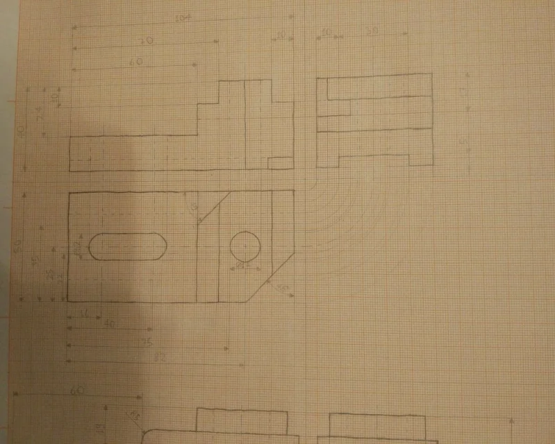
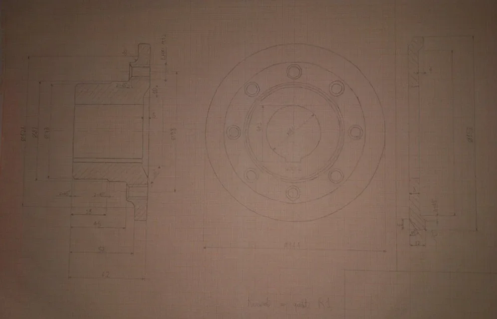
Hi, I should share these two pieces technologically.
I wanted to ask you if the quotation was correct.
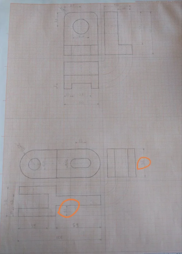
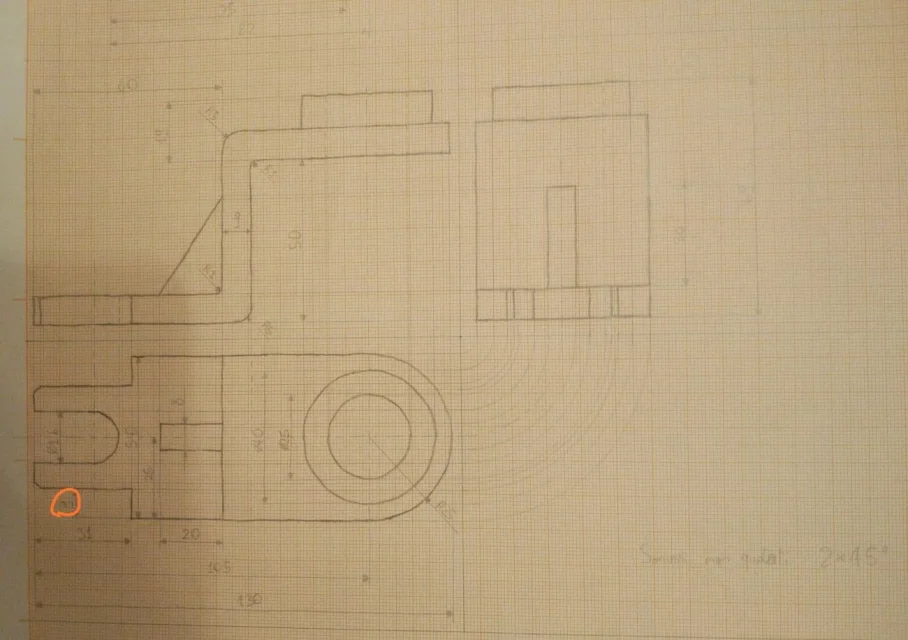
I also have two doubts about the two circled areas in the second piece:
in particular I wanted to know if it was correct to repeat twice the same quota as the width is equal to the height (as I did on the side view of the second piece), while on the plant I put the quota of 13 only on one side being the symmetric piece, is it right?
Thank you in advance for the answers
 

Attachments

  • IMG_20200107_135958.webp
    IMG_20200107_135958.webp
    47.3 KB · Views: 87
  • IMG_20200107_135944.webp
    IMG_20200107_135944.webp
    127.7 KB · Views: 98
in the design at the top I would quota the position of the hole and the lateral dig from the center and the base of support of the team, this imagining the functionality of the piece.
if instead you have listed on the side for some functional reason the speech changes.
in the piece in the bottom same speech, I would eliminate the 13 in the circle and I would quota the thickness of the piece from the center.
the 38 in the red circle must be put, unless you go to quota the other side indicating that it is a square with the appropriate symbol.
the quotas that define asola and hole.
 
substantially correct.

in the figure below:
the 13 identifies the position from the edge, but it is not specified how thick the body is
the third view is useless and that 38 circled take it to the left view

in general:
it would be more correct to bring quotas externally to geometry.
if a size is symmetrical it tracks a half-car axis (see quotas 28, 18, 12) so that they are these only functional quotas and not even those from the piece board
 
thank you very much for the answers and advice.
then in the first drawing I put the height of the hole from the base of the piece.
then in the second drawing I add the axis of symmetry on the plant.
I have not understood however if I have to add the remaining thickness in addition to the quota of 13 or is not necessary and can be obtained knowing that the total thickness of the piece is 38.
the third view I made it because it was expressly asked in the track being one of the first exercises.
One last thing, are the odds of the hole rod correct?
Thank you very much.
 
I have not understood however if I have to add the remaining thickness in addition to the quota of 13 or is not necessary and can be obtained knowing that the total thickness of the piece is 38.
look how the design of the exercise is quoted... in the end you have to insert those, it makes no sense to invent other terms of quotation

in a design have priority functional quotas, i.e. those that serve to obtain an object that carries out the purpose for which it was developed.
starting from the concept that an operator should not make calculations to obtain the dimensions to the construction of an object, but in a symmetric piece or where the functional dimension is symmetric to the half-work the non-functional measures (your 13 in this case) can be omitted.
this because the dimensions are never the hypothetical drawing ones and always have a margin of error, the so-called tolerance; binding a functional dimension through another quota implies that this too is subject to the margin of error; if instead reference to the half-carry will be only the functional quota to be subject to tolerance.
in your case with the mid-range line you are telling the operator that the size 18 and 12 will have to be symmetric and implicitly you will give an agreement between these two quotas, if then from the edge one is 13,5 and the other 10,5 will not matter
 
Last edited:
Sorry to bother again, but I have other doubts about a new design.
(I know that the odds are poorly arranged, but I had no space).
I wanted to ask if it was correct to quote in that way the bevel of the second drawing without using the word "x 45°" not being a tree.
while instead in the first drawing I wanted to ask if it was correct to indicate the distance from the edge (the 9 circled) rather than the remaining thickness.
I quoted the 9 hypothesized milling workmanship and therefore felt it more appropriate to quote the thickness to be removed rather than the remaining thickness right?
 

Attachments

  • IMG_20200107_204215.webp
    IMG_20200107_204215.webp
    65.8 KB · Views: 48
  • IMG_20200107_204241.webp
    IMG_20200107_204241.webp
    78.7 KB · Views: 41
  • IMG_20200107_204022.webp
    IMG_20200107_204022.webp
    132.5 KB · Views: 65
  • IMG_20200107_203816.webp
    IMG_20200107_203816.webp
    187 KB · Views: 48
for the bevel can also go well, but there is a quota that defines how big the bevel is.
for the second question is the speech made for the previous exercise, better insert a symmetry axis and quota the width of the appendix.
If you say how you've made the rest of the work to that 9. If, for example, the piece was obtained from a fusion maintain the 9 in tolerance could bring you the appendix out of center, inflating the alignment with the hole that should be functional to the use of the piece.
 
I wanted to ask if it was correct to quote in that way the bevel of the second drawing without using the word "x 45°" not being a tree.
Who said the x45° only goes on the trees? and anyway in your design I see "only" the x45° without size.
while instead in the first drawing I wanted to ask if it was correct to indicate the distance from the edge (the 9 circled) rather than the remaining thickness.
is the same concept that I explained in the previous post
I quoted the 9 hypothesized milling workmanship and therefore felt it more appropriate to quote the thickness to be removed rather than the remaining thickness right?
is wrong because you do not indicate at least one of the other dimensions.
However you do not have to reason for how it is obtained, but for functional dimensions; that piece you get it from bending and prepare already shaped
 
ah ok then with regard to the bevel put directly 22x45°, the quota is to be put in axial direction therefore in "horizontal" to understand us right?
while instead regarding the other design I did not understand very well: it is better to quote the distance from the axis and to quote the "remanent" thickness right?
 
I correct myself:
theoretically it is obtained from bending, but not this as the sheet of thickness 9 does not exist and it would not be possible to have an internal radius from 1 and the external one from 5 (the outside is always the sum of the internal one + the thickness)
Then I wonder, the drawing is already quoted, why do you keep inventing things? put the quotas you read
 
ah ok then with regard to the bevel put directly 22x45°, the quota is to be put in axial direction therefore in "horizontal" to understand us right?
I don't know.
while instead regarding the other design I did not understand very well: it is better to quote the distance from the axis and to quote the "remanent" thickness right?
or quoti the width crossed by the axis (the operator will know that it will have to do it 32 wide on the piece center) or quoti two dimensions. which is right? depends on what that piece needs. If you don't know, both methods are fine.
If you want to add a non-functional dimension you can put it in brackets.
because technological quotation is required
and that of the 3d design what would it be?
 
we start from the first drawing:
*view at the top left:
- 19 is wrong because it doesn't make sense to quote that thickness and however you must indicate to the operator how thick the ring to be soldered
.you do not know how wide the wing of the left s; must be inserted to allow a dimensional control and I would put in parentheses the total 130 as the sum of the three measures (60+9+61)
- the rib should be listed in this view so that it is immediately clear what its size is without the operator jumping from one view to the other
*view to the right of intuile fact, but if it is done,,
*low view:
-the length and center of the asola
-Low the share of the bevel 2x45°
 
second drawing:
*view at the top left:
on the lower right corner there is a rectangle that you do not understand what is
*view at the top right:
-that portion of the throat should be put on the other side because in that position they are far away and cross the particular
- quota 17 is wrong; if you quoted as drawing this did not happen
* low view:
- 35 is wrong; is a resultant quota and does not serve the operator
-- the 22 should be put on the other side because it is too far, crosses the particular and you do not understand what it refers to
-no hole position

correction also on 3d design:
the position quotas of the asola should almost never be put like this (rare the cases in which it is required), but the intersection or the length of the asola
These 3d are a little quoted to dog to tell the truth
 
Here I am again: lol:.
I wanted to ask you if this exercise is done correctly?
in particular I had two doubts:
1)I believe that the 124 diameter share is wrong.
2) In the view from above I put the quota 47,3 is correct or would it be better to approximate to 47?
Thank you very much
 

Attachments

  • IMG_20200111_213638.webp
    IMG_20200111_213638.webp
    62 KB · Views: 46
  • Immagine.webp
    Immagine.webp
    59 KB · Views: 44
the d124 share of the left view does not understand what it refers to
missing the axis and reference of section
no indication of the number of holes and the layout
if 47,3 is the size that must have the hole with the key* that must be; the design must report the measures you want to achieve, tendingly you plan already with finite quotas. in principle if a quota with decimals is a result of other dimensions (typical case is the cateto of a angle sized with the other cateto + corner) you can round, in carpentry round the size of the rough piece, never round the processed dimensions. * that quota is subject to the legislation on tabs.
- in the left view lacks the diameter of the lower right and the 10 is useless because it is a result of the angle for catetus 5 (in fact the operator does a deep turning 5mm up to the diameter??? and then goes out with inclination 30° and does not care if 10, 12 0 20)

- in the right view lacks the diameter of the hole and is a section rained from the sky without reference and a primary view
 
Okay, thanks again.
regarding the holes I wrote in section view 8 holes m12 is not correct?
the last drawing on the right refers to the other piece
 

Forum statistics

Threads
44,997
Messages
339,767
Members
4
Latest member
ibt

Members online

No members online now.
Back
Top