• This forum is the machine-generated translation of www.cad3d.it/forum1 - the Italian design community. Several terms are not translated correctly.

rotational dynamics

andrea_botti

Guest
Good morning to all,
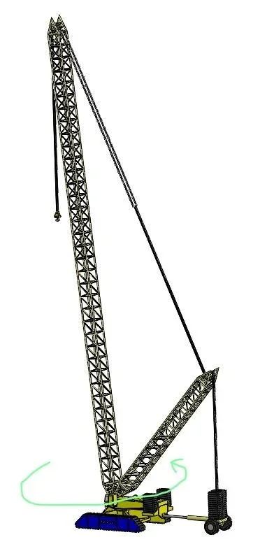
I have to realize the dynamic simulation of the rotation of a crane, I am using solidworks simulation 2019 and I need to understand how to apply the load in question.
I have already simplified the component with a single-dimensional element having the same stiffness of the arm and on this element I applied an impulsive load to see the vibrations. At this point I must combine the impulsive load with rotation to evaluate further effects of vibration.
 
Bye.

It is always a good thing to post images of what you describe and the level of modeling you have achieved.

So it seems to me that it is not a structural analysis.

if your intention is to find your own frequencies and any resonance you do not need to apply loads. frequencies and proper ways are uniquely determined by the mass characteristics and stiffness of your system
I realize in fact that I was unclear, I press that the modal analysis I have already done, I try to explain myself better:

the initial goal was to design the crane that you see in the first image attached. After all static simulations I have come to the model of the first image, at this point I have to perform dynamic checks, specifically the application of the load according to different curves (impulse, steps, climbing ramp and descent...), however being the main arm very complex (you see it in the second image and it is the object of the analysis) we decided to assimilate it to a simpler element having the same rigidity, as seen in the third figure.

now made this premise, I did the first analysis by putting a vertical force that precisely varied as pre-established and I got graphics like the one reported in the fourth figure for example following an impulse.

My doubt is as follows:
I have to do a simulation where I have the application of the vertical load, following the rotation of the arm and therefore the application of the force of inertia, the discharge of the force of inertia and the discharge of the vertical load, as in the fifth figure. in the first line I could be content with the application of the inertia force without vertical load. my question is therefore how can I do with solidwork simulation at phase this thing?
 

Attachments

  • Annotazione 2020-08-19 203023.webp
    Annotazione 2020-08-19 203023.webp
    28 KB · Views: 16
  • Annotazione 2020-08-19 204040.webp
    Annotazione 2020-08-19 204040.webp
    11.8 KB · Views: 19
  • Annotazione 2020-08-19 203145.webp
    Annotazione 2020-08-19 203145.webp
    10.3 KB · Views: 18
  • Grafico1.webp
    Grafico1.webp
    57.6 KB · Views: 17
  • Immagine1.webp
    Immagine1.webp
    10.1 KB · Views: 15

Forum statistics

Threads
44,997
Messages
339,767
Members
4
Latest member
ibt

Members online

No members online now.
Back
Top