gio_deere
Guest
Hello everyone,
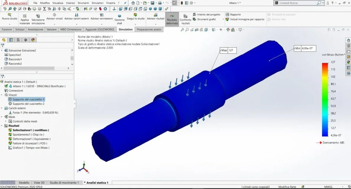
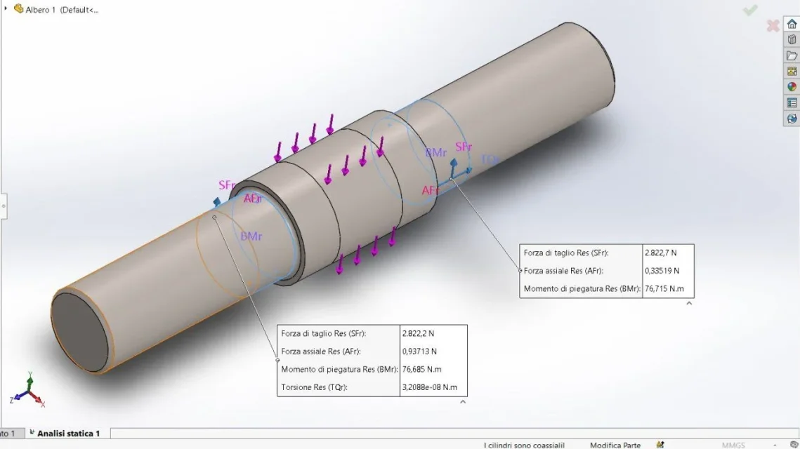
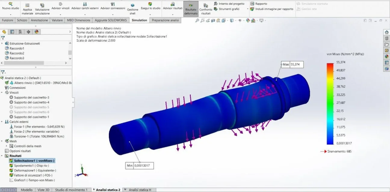
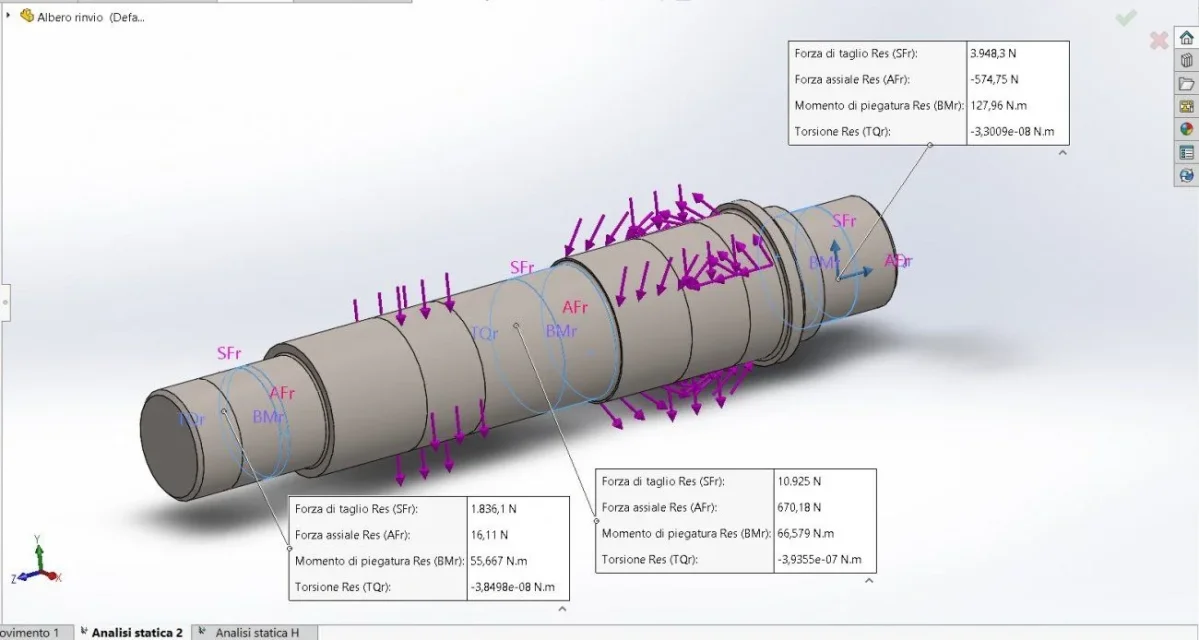
Excuse me if I write after a long time, but I was busy with the last (hopefully?) exam. as I had already mentioned in the following tread, I'm continuing my thesis work on a reducer. Now I'm focusing on static tree simulation. After I was informed and see how to set constraints and forces, I put myself to work. the trees to simulate are 3, respectively an input tree, one of reference and one of exit. for the application of forces I have based on static patterns of beams (hand solved of which I attach drawings and calculations [Estratto 2]). Based only on the forces of reaction to the constraints (I used the bearing bond) I find myself only with the first two trees. in the output shaft, problems are encountered, perhaps linked to the definition of the forces (it does not correctly execute the simulation and goes in error) . regarding the stresses, the problem of understanding with which data to compare them. I also allego the fatigue test of the trees [Estratto 3].
what I ask is to direct or advise me if I am going on the right path.
if it can be useful I explain briefly how I set forces and constraints:
1) I used the division line command to locate the portions of the shaft that will accommodate the bearings and wheels
2) with regard to the forces, I applied the result of perhaps radial and tangential vertically, the axial forces along the axis, while where there was an eccentric bending moment, I applied a torque compared to a perpendicular axis of the tree, trying to simulate the pure moment (because in solidworks there is no specific command)
if you need to explain something else do not hesitate to ask me. I thank all those who will help me in advance?
(I attach extracts and screens)