Iason
Guest
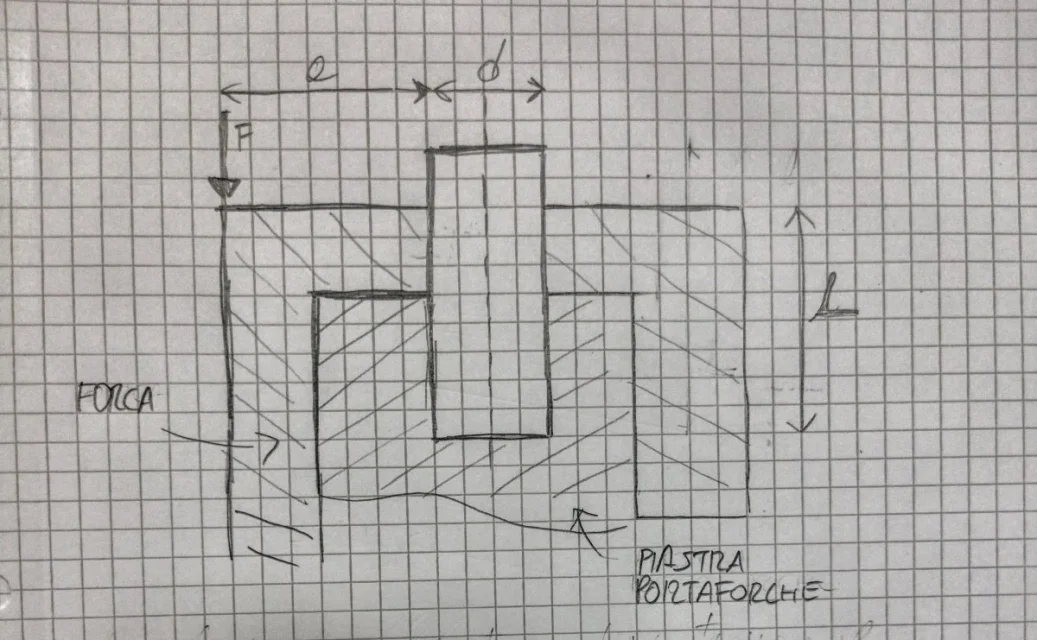
good evening to all, I would have a question to ask you, I am preparing a project for the construction examination of machines for the three-year mechanical engineering. specifically I am designing the lift group of a forklift. are in difficulty with the sizing of the pin that prevents the translation of the fork against the fork holder. I have the possibility to choose from catalog the components but I would like to justify the choice made with considerations on the loads agents on the pin. would you tell me how to approach the problem? I attach an indicative pattern, where f represents the load on the fork. I ask forgiveness in advance for the dissatisfaction of the question, unfortunately after doing the second year including construction science I left the university for almost ten years and so at the moment I have big gaps on it.
Attachments
Last edited:


