volaff
Guest
Hello everyone, it is the first time I write in this section but not the first in the forum.
I'm a mechanical engineering student that Tuesdays I have to support the writing of the oleodynamic and pneumatic examination.
I have a question maybe a little stupid but not having followed the course I have a big doubt.
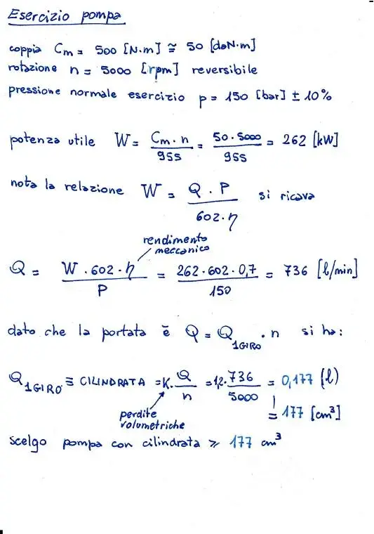
I attach the exam track and the relative solution I have made (please that the exercise is of examination but there was a block already carried out of exercises that the prof recommended) but without the attached catalogs for which I improvised.
to here everything more or less well.
the problem arises when, speaking with a friend, he told me that at the examination the prof also wants the sizing of the suction tube and sent.
I don't know how to do it. I suppose a given type of flow and pressure should be provided, but then? ?
I know that at the esmae the prof from also tube catalogs but how do I use them?
Can someone help me?
Thank you very much in advance
I'm a mechanical engineering student that Tuesdays I have to support the writing of the oleodynamic and pneumatic examination.
I have a question maybe a little stupid but not having followed the course I have a big doubt.
I attach the exam track and the relative solution I have made (please that the exercise is of examination but there was a block already carried out of exercises that the prof recommended) but without the attached catalogs for which I improvised.
to here everything more or less well.
the problem arises when, speaking with a friend, he told me that at the examination the prof also wants the sizing of the suction tube and sent.
I don't know how to do it. I suppose a given type of flow and pressure should be provided, but then? ?
I know that at the esmae the prof from also tube catalogs but how do I use them?
Can someone help me?
Thank you very much in advance

")