• This forum is the machine-generated translation of www.cad3d.it/forum1 - the Italian design community. Several terms are not translated correctly.

steel column size

  • Thread starter Thread starter Ing.Vedder
  • Start date Start date

Ing.Vedder

Guest
Hi, everyone, I'm going back to a topic from which I hope someone can pull me out, as I alone don't step forward. .
I need to understand, once and for all, how to evaluate a coefficient of free inflation for steel columns. .
the theory of coefficients based on hinge etc 0.7,1,2 we all know it, but then in practice?
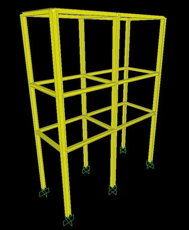
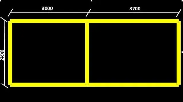
stupid example of terlaio 3d.
each of the 3 floors will be trampled (live boxes) and will hold pipes (dead boxes).
exists a unique way to establish what coefficient of free inflection consider for the 6 columns of the frame?
How do I behave?(They also told me that the length of free inflation is calculated by performing a buckling analysis of the structure but I didn't understand much more)
At the base I'll have some basic plates, so considering them stuck, it seems to me a correct approximation, but for the rest I would like someone to explain to me how to proceed. .
help, please..do realize talking to a child of the elementary school...I tried to read everything possible but I did not find a clear and simple explanation on how to do it.

Many thanks to all.
Ing. vedder
 

Attachments

  • EXAMPLE1.webp
    EXAMPLE1.webp
    39.6 KB · Views: 26
  • EXAMPLE2.webp
    EXAMPLE2.webp
    7.8 KB · Views: 18
  • EXAMPLE3.webp
    EXAMPLE3.webp
    4.6 KB · Views: 17
ing. vedder, you have to read the entry 2008 and design the structure according to Eurocodes (please!!!!).
Everything you're talking about from where you got it?
or use eurocodes or use cnr10011 even if withdrawn.
Hi.
 
thank you gerod, fortunately I do not have to subject to any norm in particular, only sometimes I happen to have to dimension structures of this type and I would like to make a sensible and consistent dimensioning.
If we follow the aun 1011 the only thing he says is what we all know. .

1 if the rod is hinge-pick
0.7 if incastro-incastro
0.8 if incastro-cerniera
2 if incastro - free

Here. a little vague, hardly in practice I will find myself in such a situation..I would like to understand how to consider my columns of the example. I see them as columns framed at the base and with restraints to the lateral shift from time to time (the plans of my construction)
I would like to understand how to proceed in reasoning to make a sensible sizing, that's all.

Thank you!
 
Fortunately I do not have to submit to any norm in particular
I disagree. if you have to design any structure you are obliged to follow the norms ntc2008 and therefore Eurocodes. Remember that in case of dispute you must demonstrate the goodness of calculations.

cnr10011 is still used but I would be careful and update. that rule simplifies things so you have to be good at understanding what coefficient to take.
 
thanks gerod, the fact that it is necessary to use a soono rule perfectly agree with you. I just meant that the customer does not bind me to follow any, so I to make a sensible sizing but not too laborious I wanted to use the 10011 which is certainly the easiest interpretation. My problem is, as I told you, to evaluate the free length of inflection, a data often underestimated but that leads to completely different sigma values based on how it is considered.

Thanks again for the help
 
what gerod says is right, but those rules do not apply to "any" structures. for example if I have to dimensional the barrel of a motorcycle that I do?

Welcome to the fantastic world of instability.

let's see before we understand what the length of free inflation is. take a beam, charge it at a certain point undergoes a lateral shift. the elastic line of the striped beam will present some fluctuations, the wavelength of the oscillation is the length of free inflection. That's all. If you're doing two building science accounts, you'll see where those numerals come from.

for the structure that you have posted, I would strongly advise you to follow such an approach. Instability analysis (or buckling) is of a global, non-local type type. it would be to say that it is not enough to find the most stressed section and to dimension it, but it is always necessary to consider the whole structure.
to explain myself better. Imagine putting a couple of elephants on the top shelf, do your good accounts, every piece of beam has its length of free inflection, size the section and....sbagli! because when you go to load you will really find that the plans will stand out between them (they will not be superimposed if seen in the plant) and all your chills go to...insomma to palace pretty!

many fems do buckling analysis, who better, who worse, but what for you is very difficult to imagine, and instead the most fetente fem calculates egregiamente and the unstable configuration of minimal energy, that is the first that collapses the structure. the advice that I can give you is to make a model, make it turn under analysis of instability, and from there see the destiny of the structure and the lengths of free inflection. then with this data do the calculations as they are the best thing if you do not have extreme familiarity with the fem.

Sorry about the wear
 
I would like to thank you enormously. :eek:
Your answer has been clear to me and the wear is honey for my ears.
the concepts you expressed were all more or less known to me but in the head I have a lot of confusion about it. tomorrow I promise to reread carefully and develop the problem with the guidelines you indicated me.
I hope I can hear you again about this.. I have a lot of confusion about instability and being able to compare with someone who knows it fills my heart with joy::biggrin:

Thanks again

ev

for example, the first two questions that come to mind about it (I "mastic" know 2000, I don't know if you are practical)

I have to do a buckling analysis and I know it's okay.

but:

1)The buckling analysis should be done by loading the structure with dead and live loads, or the way to unstable any structure is regardless of how this is loaded?

2)There are various ways of instabilizing, precisely know how to find 6 ways of instability, I care about the first?

infinitely grateful

ev
 
That's what I gave birth. I would be very happy if Roman lightning that helped me so much about it could take a look at it and give me two tips... at least to understand if I'm thinking correctly. . .
clearly anyone who has to say his is highly recommended to do it!


thanks to all

ev
 

Attachments

Therefore, I make some comments, but I would pray all the forum to deny myself if necessary, because I am not an strutturist.

I think buckling analysis is independent of loads. Try to turn off the loads and see if something changes. in particular see if factors and arrows change

- the [primi] Six ways of instability are the ways of vibration of the structure. if you do not take dynamic (type structural dampeners) and if there are no rigid appendixes, in principle you only care about the first way to vibrate

- the high factor I don't know what it is, but I think it's tied up or the energy needed to vibrate the structure with that particular way, or the frequency of free oscillation. as a "factor" should be adimensional, so better see the sap manual to understand what it is.

- be careful that the analysis of instability is relative to the whole structure, you want the length of free inflection only of a piece. This is conceptually wrong, but if you are clear why, you can proceed with your reasoning.
careful that to evaluate the length you have to consider the corners of the elastic line. your reasoning is right if you have fi = 0 up there. otherwise the oscillation actually continues. I try to attach something useful.. .
 
I don't know.
for fun, try to continue the blue beam up to have more than one full wave, it should be easier to measure the free length of inflection. . .
 
Then lightning,
first of all thanks also only for the profuso commitment.
I'm back to work now and I'm devouring your considerations, as soon as I have a moment of time I try to make all the checks you say.

infinitely thanks again

ev
 
I think buckling analysis is independent of loads. Try to turn off the loads and see if something changes. in particular see if factors and arrows change
I confirm they change. to decrease the loads the numeral increases, sign of a greater energy necessary to make it unstable. At least I guess.
- i [primi] Six ways of instability are the ways of vibration of the structure. if you do not take dynamic (type structural dampeners) and if there are no rigid appendixes, in principle you only care about the first way to vibrate
received, as I imagined
- be careful that the analysis of instability is relative to the whole structure, you want the length of free inflection only of a piece. This is conceptually wrong, but if you are clear why, you can proceed with your reasoning.
careful that to evaluate the length you have to consider the corners of the elastic line. your reasoning is right if you have fi = 0 up there. otherwise the oscillation actually continues. I try to attach something useful.. .
I understand, but I can't assess if I have fi=0. .
I'm confused. .
 
I found This is an example that deals with the subject.. and more or less follows the method that you have indicated to me... but to him come out of the perfect sinusoidal deformities, easy to count and therefore easy to detect..to me comes out a bowl.
look at page 12(low+13) and page 24-25-26.

thank you once again

ev
 
have you tried to prolong the column to have a longer length on which to observe the oscillations?
However, the problem is more complex than expected, and I'm not a strutturist... .
 
what gerod says is right, but those rules do not apply to "any" structures. for example if I have to dimensional the barrel of a motorcycle that I do?

Welcome to the fantastic world of instability.

let's see before we understand what the length of free inflation is. take a beam, charge it at a certain point undergoes a lateral shift. the elastic line of the striped beam will present some fluctuations, the wavelength of the oscillation is the length of free inflection. That's all. If you're doing two building science accounts, you'll see where those numerals come from.

for the structure that you have posted, I would strongly advise you to follow such an approach. Instability analysis (or buckling) is of a global, non-local type type. it would be to say that it is not enough to find the most stressed section and to dimension it, but it is always necessary to consider the whole structure.
to explain myself better. Imagine putting a couple of elephants on the top shelf, do your good accounts, every piece of beam has its length of free inflection, size the section and....sbagli! because when you go to load you will really find that the plans will stand out between them (they will not be superimposed if seen in the plant) and all your chills go to...insomma to palace pretty!

many fems do buckling analysis, who better, who worse, but what for you is very difficult to imagine, and instead the most fetente fem calculates egregiamente and the unstable configuration of minimal energy, that is the first that collapses the structure. the advice that I can give you is to make a model, make it turn under analysis of instability, and from there see the destiny of the structure and the lengths of free inflection. then with this data do the calculations as they are the best thing if you do not have extreme familiarity with the fem.

Sorry about the wear
finally an ing. with attributes!! :cool:
Say hello,ziotoy.
 

Forum statistics

Threads
44,997
Messages
339,767
Members
4
Latest member
ibt

Members online

No members online now.
Back
Top